
SFM decides how fast the cutting edge meets the work. Set it right and tools last, surfaces clean up, and cycle time drops. Set it wrong and you either burn the tool or work-harden the part. This guide covers the formula, RPM conversion, HSS vs carbide speed charts by material, coating effects, and the setting mistakes that damage tools.
Ⅰ. What Is SFM in Machining?
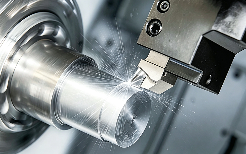
SFM (Surface Feet per Minute) is the linear speed of the cutting edge relative to the workpiece surface, measured in feet per minute. It is a material property — aluminum wants a higher SFM than titanium regardless of which machine runs it.
The common confusion is between SFM and RPM. SFM describes how fast the cutting edge travels through the material. RPM describes how fast the spindle spins. Two tools running the same RPM at different diameters produce different SFM values. This is why a 1/4-inch end mill and a 1-inch face mill need different RPM settings to hit the same SFM target.
SFM, or Surface Feet per Minute, is a foundational parameter for all metal cutting work. Reasonable SFM values minimize tool abrasion, enhance workpiece surface quality and maintain stable machining efficiency in mass CNC manufacturing.
Ⅱ. SFM vs RPM: Formula and Conversion
SFM is set by the material. RPM is set by the tool diameter. The conversion between them is a single formula in two directions:
RPM = (SFM × 3.82) / D (D = tool diameter in inches)
SFM = (RPM × D × π) / 12
The factor 3.82 comes from 12 / π, which converts between feet-per-minute and the circumference calculation in inches.
Worked Examples
Example 1 — Aluminum 6061 with a 1-inch carbide end mill
Target SFM = 1000
RPM = (1000 × 3.82) / 1 = 3820 RPM
Example 2 — Stainless 304 with a 0.5-inch HSS end mill
Target SFM = 60
RPM = (60 × 3.82) / 0.5 = 458 RPM
The One Mistake That Quietly Ruins Tools
The same SFM value produces a different RPM for every tool diameter. When an operator swaps a 0.5-inch tool for a 0.25-inch tool without recalculating, the actual cutting speed can drop by half or double — either starving the cut or burning the edge. Recalculate RPM every time the tool diameter changes.
Ⅲ. Why SFM Matters: Heat, Tool Life, and Surface Finish
SFM sets the cutting temperature. Everything else — tool life, surface finish, cycle cost — follows from that one variable.
Too high: The cutting zone overheats. The edge softens, wears fast, and can plastic-deform. On stainless and titanium, you also get work hardening ahead of the cut, which accelerates wear further. Surface discoloration (straw to blue) is the visible signal.
Too low: The tool rubs instead of cuts. Friction heat builds without material removal, which work-hardens the surface and dulls the edge. For stainless and titanium, running below the recommended floor is often worse than running slightly above it.
Three Downstream Effects
- Heat and tool life — Carbide edges tolerate roughly 800–1000°C before degradation; HSS fails far lower. Every excess SFM shortens edge life disproportionately.
- Surface finish — Built-up edge (BUE) forms in a narrow temperature band. Wrong SFM pulls weld material onto the edge and tears the surface.
- Cycle cost — A conservative SFM adds minutes per part. On a 500-part run, 30 extra seconds per piece is over four hours of lost capacity.
Ⅳ. Recommended SFM for Common Materials
The table below lists baseline SFM ranges for uncoated tools. Actual cutting speed depends on coating, geometry, and machine rigidity — covered in the next section.
| Material | HSS (SFM) | Carbide (SFM) |
|---|---|---|
| Aluminum 6061 | 300–1000 | 800–1500 |
| Mild Steel 1018 | 60–100 | 300–600 |
| Stainless 304 | 40–80 | 150–400 |
| Stainless 316 | 40–70 | 120–350 |
| Titanium Ti-6Al-4V | 20–40 | 50–150 |
| Cast Iron | 50–80 | 200–450 |
| Brass | 200–400 | 600–1000 |
| Copper | 100–200 | 500–800 |
| Tool Steel | 40–70 | 150–300 |
| Inconel 718 | 10–20 | 30–90 |
Carbide runs 2–4× faster than HSS on the same material. Mixing the two columns — running a carbide tool at HSS speeds, or pushing HSS into the carbide range — is the most common cause of early edge failure.
Ⅴ. Factors That Affect Recommended SFM
The baseline ranges assume an uncoated tool on a rigid machine. Real cuts deviate based on the following:
Tool Coating
Coating is the single largest SFM multiplier after the base material. Use the table below to adjust the baseline upward.
| Coating | SFM Increase | Best Use |
|---|---|---|
| TiN | +15–25% | General steel milling |
| TiAlN | +30–50% | High-speed dry machining |
| AlCrN | +35–50% | High-temp alloys, hard steels |
A coated carbide end mill running TiAlN on aluminum 6061 can reach 1500–2250 SFM — well above the uncoated baseline.
Tool Geometry
Flute count, helix angle, and rake angle change how the tool engages the chip. More flutes allow higher feed rates but do not raise the SFM limit. A high-helix tool evacuates chips better in aluminum, which lets you push the upper end of the range.
Depth of Cut and Radial Engagement
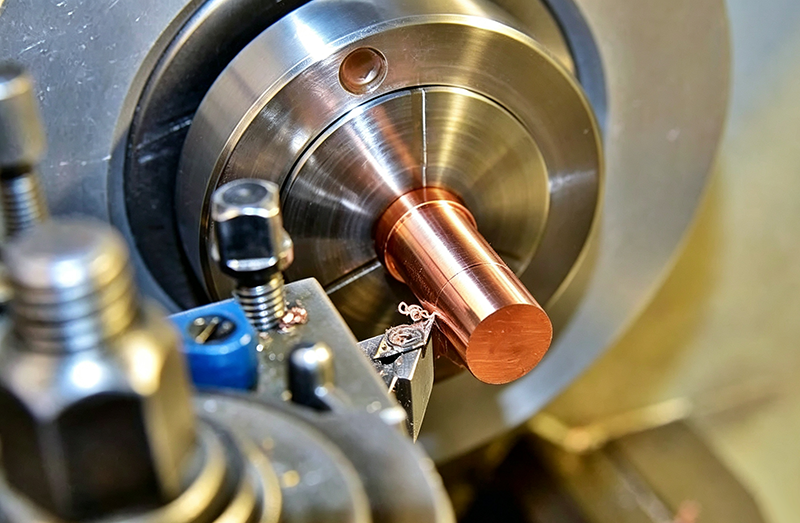
Heavy radial engagement and deep cuts concentrate heat. Drop SFM 20–30% for full-width slots or depths exceeding 1× diameter. Shallow finishing passes can run at the top of the range.
Coolant
Flood coolant extends the usable SFM window on steel and stainless. For aluminum and titanium, mist or air blast often outperforms flood — thermal shock on carbide can crack the edge.
Machine Rigidity
Older spindles, extended tool holders, and long overhangs reduce stiffness. Chatter marks mean the SFM is too high for the setup. Drop 20–30% from the baseline when rigidity is uncertain.
Ⅵ. Roughing vs Finishing SFM
Roughing and finishing have different goals. Roughing prioritizes material removal and tool life — lower SFM, deeper cuts, heavier chip load. Finishing prioritizes surface quality — higher SFM, lighter cuts, cleaner edges.
| Material | Roughing Carbide SFM | Finishing Carbide SFM |
|---|---|---|
| Aluminum 6061 | 800–1000 | 1200–1500 |
| Mild Steel 1018 | 300–400 | 450–600 |
| Stainless 304 | 150–250 | 300–350 |
| Titanium Ti-6Al-4V | 50–80 | 100–120 |
Finishing SFM sits higher because chip load is lighter and heat disperses faster. The gain varies by material — aluminum and mild steel tolerate the widest finishing-to-roughing gap, while titanium and stainless narrow it. Always verify the finishing pass on scrap stock before committing to production.
Ⅶ. Common SFM Mistakes and How to Avoid Them
- SFM set too high — Edge burns, surface discolors, tool fails within minutes. Fix: Start at the lower end of the range, watch chip color, and step up only if the cut is clean.
- SFM set too low — Rubbing replaces cutting, work hardening on stainless and titanium, edge dulls anyway. Fix: Stay above the material’s floor. For stainless, slightly high is safer than slightly low.
- Same SFM for HSS and carbide — HSS burns at carbide speeds; carbide wastes cycle time at HSS speeds. Fix: Use the correct column. When switching tool materials on the same job, recalculate.
- Ignoring coating potential — A coated tool runs at uncoated speeds, wasting the cycle-time gain the coating was bought for. Fix: Apply the coating multiplier from the table. A TiAlN-coated carbide end mill on steel should run 30–50% faster than the uncoated baseline.
- Not recalculating RPM after tool change — Actual SFM drifts by 2–3× when diameter changes. Tool life becomes unpredictable. Fix: Run the formula every time you change tools. Program a calculator macro in the CAM or machine control.
- Ignoring machine rigidity — Chatter, poor surface finish, and chipped edges on older or lightly-built machines. Fix: Drop SFM 20–30% on setups with long overhang, worn spindles, or undersized tool holders.
Ⅷ. How to Use Manufacturer SFM Data
Tool catalogs from Kennametal, Sandvik, and Iscar publish SFM ranges, not single values. Those ranges are starting points — they assume a rigid setup, ideal coolant, and a fresh edge. Real conditions rarely match all three.
Range vs Starting Value
Most catalogs list a low and high value. The low end is for conservative setups: long overhang, older machine, mixed material condition. The high end assumes a stiff machine, short tool, and consistent workpiece prep.
When to Trust the Catalog vs When to Test
Trust the catalog for established material-tool pairs (carbide on mild steel, HSS on aluminum). Test when any of the following apply: new coating on a new alloy, long overhang over 3× diameter, thin-wall part, or a material certification you have not run before.
Vendor Differences
Catalog values can vary 10–15% between vendors for the same material-tool combination. This is normal — vendors optimize for their own substrate and coating stack. When two catalogs disagree, start at the lower intersection and test up.
Ⅸ. Conclusion
SFM is a material property, not a spindle setting. Carbide runs 2–4× faster than HSS on the same material, and coating can add another 30–50% on top. Machine rigidity, depth of cut, and tool geometry all adjust the baseline. The mistake that wastes the most tools is failing to recalculate RPM when the tool diameter changes — run the formula every time.
Getting SFM right is part of a manufacturability review, not just a feeds-and-speeds exercise. Keywin’s CNC engineers verify material-tool-SFM matches during quoting, so cutting parameters are locked before the first cut, not corrected after the first failed part. Get an instant quote for your CNC project with a free DFM review.
FAQ
1. Should I start at the high or low end of the recommended SFM range?
Start low when machine rigidity, tool holder condition, or workpiece fixturing is uncertain. Move up only after the cut runs clean — chips form properly, surface is stable, and the tool sounds consistent.
2. Can I use the same SFM for HSS and carbide tools?
No. Carbide tolerates 2–4× higher SFM than HSS on the same material. Running HSS at carbide speeds burns the edge; running carbide at HSS speeds wastes cycle time.
3. How does tool coating change the SFM I should run?
TiN adds 15–25%, TiAlN adds 30–50%, and AlCrN adds 35–50% to the uncoated baseline. The multiplier applies to the base material’s SFM range, not to RPM directly.
4. Why does my tool wear faster than the SFM chart predicts?
Check machine rigidity first — long overhang and worn spindles are the most common cause. Then verify coating match, coolant delivery, and that RPM was recalculated for the actual tool diameter.
5. Do I need to recalculate RPM when I change tool diameter?
Yes. RPM depends on both SFM and diameter. A 0.25-inch tool needs twice the RPM of a 0.5-inch tool to hit the same SFM. Reusing the previous RPM is the most common cause of silent tool failure.
6. How does SFM affect tool life?
Excess SFM raises cutting temperature, which softens the edge and accelerates wear disproportionately. Below the floor, rubbing replaces cutting and work-hardens the surface, which dulls the edge through a different mechanism.