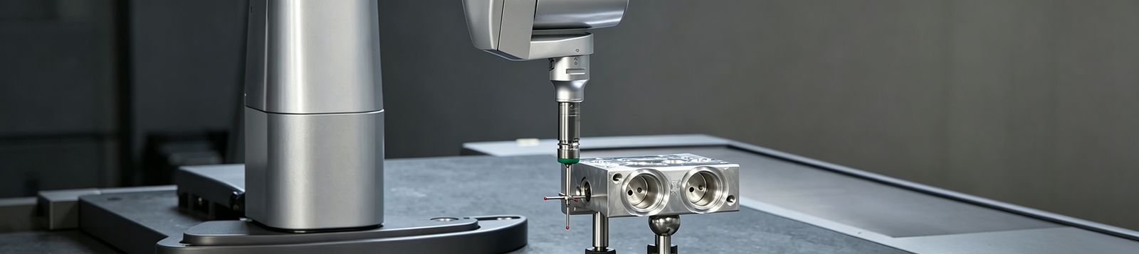
CMM inspection uses a coordinate measuring machine to collect three-dimensional measurement data from a part and compare the results with the dimensions, geometry, and tolerances specified in the engineering drawing or CAD model. This data helps determine whether the inspected features meet the defined requirements.
However, a CMM report only covers the parts and features that were actually inspected. It does not, by itself, verify material grade, hardness, surface roughness, or coating requirements; these typically require other inspection methods or supporting quality documentation. Measurement results can also be affected by factors such as part setup, datum alignment, probe selection, measurement strategy, machine programming, and inspection conditions.
Ⅰ. What Is a CMM and What Does It Measure?
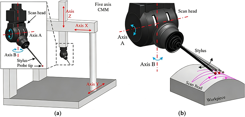
CMM stands for coordinate measuring machine. It moves a probe along the X, Y, and Z axes to capture points on a part. Metrology software then uses those points to calculate features such as lines, planes, circles, cylinders, cones, and slots. Modern CMMs may use contact probes, optical sensors, or both.
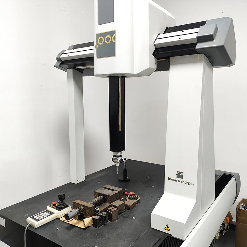
The following terms are related but not interchangeable:
| Term | What it means |
|---|---|
| CMM | The measurement equipment or system |
| CMM measurement | Probing and recording coordinate points |
| CMM inspection | Using measurement results to judge conformance to specified requirements |
| CMM report | The document that records results and, where defined, pass/fail status |
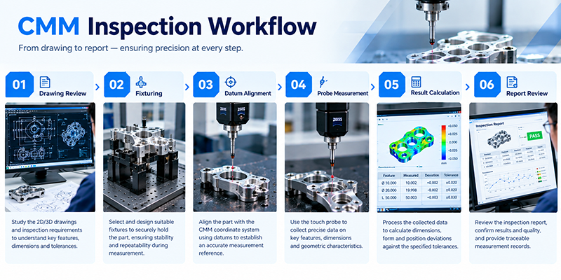
Ⅱ. How Does the CMM Inspection Process Work?
Review the Drawing and Inspection Requirements
The inspector confirms the drawing revision, units, dimensional tolerances, GD&T callouts, datum scheme, critical features, sample size, and required report format. Measuring against the wrong revision invalidates the comparison.
Prepare and Fixture the Part
The part is cleaned, deburred, and allowed to stabilize in the inspection environment. The fixture must restrain the part without distorting it, especially when the part has thin walls or is made from a soft material.
Establish Alignment and Datums
The CMM coordinate system is aligned to the datums specified on the drawing. Substituting a convenient best-fit alignment can change the reported deviations and make the results inconsistent with design intent.
Qualify the Probe and Collect Measurement Points
The probe type, stylus length, and tip diameter are selected for feature size and access. Point count and distribution must match the feature and the characteristic being evaluated; a sparse pattern may miss local form variation.
Calculate Features and Compare Results
The software calculates dimensions and GD&T characteristics from the collected points, then compares them with nominal values and tolerance limits. Fitting algorithms and filtering settings should be controlled in the inspection program.
Generate and Review the CMM Report
The report lists the measured features and their status. Before release, the reviewer confirms the drawing revision, units, datums, tolerance rules, and any borderline results.
Ⅲ. Types of CMMs Used for Part Inspection
CMM selection depends on part size, geometry, access, inspection location, and required uncertainty.
| CMM Type | Common Use | Main Limitation |
|---|---|---|
| Bridge CMM | Small to medium machined parts in a controlled room | Limited working volume and probe access |
| Gantry CMM | Large parts, dies, and structural components | Floor space, cost, and environmental control |
| Horizontal-arm CMM | Long, thin-wall parts and side features | May not suit small features with tight tolerances |
| Portable arm CMM | Large immovable parts and on-site checks | More sensitive to operator technique and environment |
| Optical or multisensor CMM | Small, soft, or non-contact features | Line of sight, reflectivity, and sensor capability |
Ⅳ. What Can a CMM Inspect on CNC Parts?
Suitability depends on feature access, size, geometry, tolerance, probe configuration, and required measurement uncertainty. CMMs support many dimensional and geometric checks on parts made through CNC machining services, but one instrument does not cover every drawing requirement.
| Inspection Task | Typical CNC features | Notes |
|---|---|---|
| Size | Hole diameter, shaft diameter, length, width | Simple accessible dimensions may be faster to check with a caliper, micrometer, or gauge |
| Location | Hole position, hole-to-hole distance, pattern center | Requires correct datum establishment |
| Orientation | Perpendicularity, parallelism, angularity | Depends on the datum scheme and point distribution |
| Form | Flatness, roundness, cylindricity | Sparse sampling may not capture local form variation |
| Profile | Free-form surfaces and contours | Requires a defined comparison model and evaluation rule |
| Feature relationship | Coaxiality, hole patterns, multi-datum relationships | Requires suitable programming and probe access |
For parts produced through CNC drilling services, a CMM can evaluate hole position, diameter, and orientation to a datum. A small, deep hole may still require a depth gauge, probe extension, or another method when access is limited.
Ⅴ. What Does a CMM Inspection Report Show?
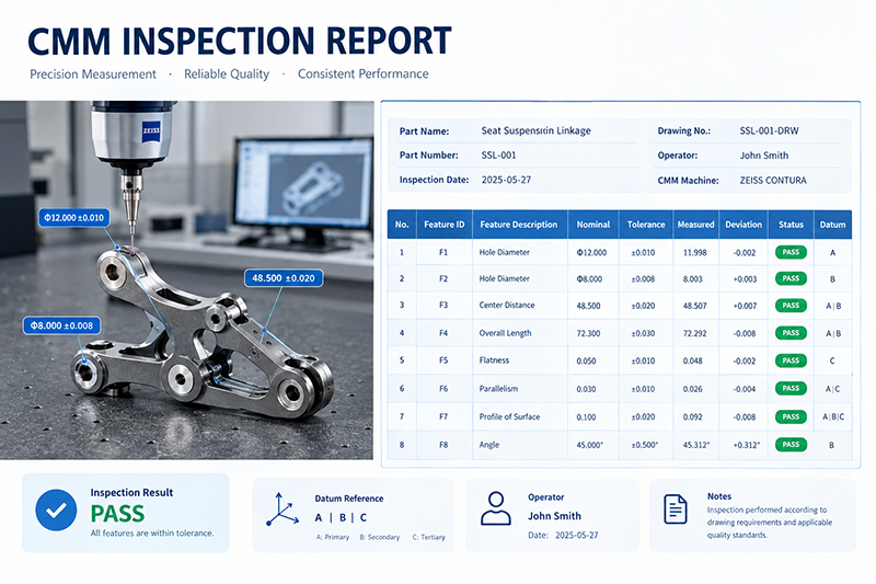
A CMM report records measured features and their comparison with specified requirements. Its value depends on the inspection plan behind it.
Typical Information in a CMM Report
A report may include the part number, drawing revision, sample ID, inspection date, units, feature ID, nominal value, limits, measured value, deviation, status, datum or alignment, and equipment or program references. The exact fields depend on customer and quality-system requirements.
What the Report Can Prove
For the features measured, a CMM report provides numerical evidence that a specific sample met or did not meet the stated tolerances under the recorded inspection conditions. It also creates a traceable record for that sample; it does not automatically establish that every part in the batch, or the process over time, will produce the same result.
What the Report Does Not Automatically Prove
The report does not automatically confirm material grade, chemistry, heat treatment, hardness, surface roughness, coating thickness, internal defects, unmeasured features, uninspected parts, or long-term process stability. Lot acceptance requires a sampling or inspection plan that covers the lot.
CMM Report vs First Article Inspection Report
A CMM report covers the dimensional results produced by the CMM. A first article inspection report may also address other drawing and specification requirements, including material and special-process records, depending on the applicable standard and customer requirements. A CMM report can support an FAI, but it does not replace the complete first article review.
Ⅵ. What Affects CMM Measurement Accuracy?
A CMM’s stated machine performance is not the uncertainty of every measurement it performs. The actual result depends on the complete measurement task.
Measurement Uncertainty, Repeatability, Resolution, and Machine Accuracy
These terms answer different questions. Measurement uncertainty is the range associated with a reported result for the defined task; repeatability describes how closely repeated measurements agree under the same conditions; resolution is the smallest displayed or reported increment; and machine accuracy or performance is the equipment specification verified under defined test conditions. A small display increment or an impressive machine specification does not by itself prove that a measurement setup is suitable for a particular tolerance. For a tight-tolerance decision, the measurement plan needs uncertainty and repeatability suited to the feature, tolerance, and acceptance risk; no single CMM accuracy value applies to every job.
Machine Performance
ISO 10360-2 defines acceptance and reverification tests for Cartesian CMMs using contact probing in discrete-point mode. These tests verify stated machine performance; they do not establish the uncertainty of every feature measured on every part.
Temperature and Environment
Part and machine temperature, temperature drift, vibration, dust, and contamination can shift results. For example, a 1 °C temperature change produces roughly 1 µm of length change over 100 mm of steel, although the exact value depends on the material’s thermal expansion coefficient.
Probe and Stylus Selection
Stylus length, tip diameter, probe qualification, and contact direction affect access and measurement behavior. Probe selection must suit the feature and inspection strategy.
Datum Alignment and Fixturing
Clamp distortion, part movement, and alignment that does not follow the drawing datums can change the reported result.
Sampling and Software
Point count, point distribution, fitting algorithm, filtering, and feature modeling affect the calculated geometry. These settings must be appropriate for the characteristic being evaluated.
Two CMM inspections of the same part can therefore produce slightly different values without either result being automatically wrong. Probe contact, point distribution, datum alignment, fixturing, temperature, and repeatability can each contribute; the relevant acceptance question is whether the measurement process has suitable uncertainty and repeatability for the tolerance being evaluated.
Ⅶ. Advantages and Limitations of CMM Inspection
| Advantages | Limitations |
|---|---|
| Measures three-dimensional feature relationships | The probe or sensor must reach or see the feature |
| Handles complex geometry and multi-datum schemes | Cycle time may be impractical for high-volume 100% checks |
| Produces recorded numerical results | Program, alignment, and sampling choices affect the result |
| Evaluates many GD&T characteristics | Some surfaces, materials, and internal features require other methods |
| Reuses a validated program for repeat orders | Thin or flexible parts may deform during fixturing |
Ⅷ.CMM vs Other Inspection Methods
CMM inspection is one part of an inspection plan. Other tools may be faster or more suitable for specific characteristics.
| Method | Best suited for | Not a substitute for |
|---|---|---|
| Caliper | Length, thickness, external diameter | Complex GD&T and multi-datum relationships |
| Micrometer | Accurate accessible thickness and diameter | Full 3D relationships |
| Pin or plug gauge | Fast functional hole checks | Detailed size and position data |
| Thread gauge | Functional GO/NO-GO thread checks | Complete thread profile evaluation |
| Height gauge | Heights and positions on a surface plate | Complex free-form surfaces |
| Optical comparator or vision system | Small edges, contours, and 2D features | Hidden 3D features |
| Surface roughness tester | Ra, Rz, and other texture parameters | 3D size and position |
| 3D scanner | Large surfaces and shape comparison | Some tight tolerances and hidden features |
| CMM | 3D size, location, orientation, and datum relationships | Surface roughness, material properties, and unreachable internal features |
For tight-tolerance CNC machining, CMM inspection may be combined with surface roughness testing, thread gauging, and visual inspection. Each method should be assigned to the characteristics it can verify reliably.
A CMM and a micrometer can give slightly different results for the same feature because they do not necessarily use the same contact method, alignment, fixturing, temperature condition, sampling location, or measurement strategy. A difference does not automatically mean one instrument is wrong; it must be considered against the specified tolerance and the uncertainty of the applicable method.
Ⅸ. When Should You Request CMM Inspection?
Request CMM inspection when the part has interrelated datums, assembly-critical hole patterns, complex GD&T, free-form profiles compared with CAD, or a requirement for a formal dimensional record. It is also useful for first article and qualification work.
A tight tolerance does not automatically make CMM the required inspection method. CMM inspection may add little value when the part has only a few accessible dimensions, a functional gauge directly verifies assembly, or a micrometer or other dedicated instrument can resolve the specified tolerance with suitable uncertainty. Requiring CMM inspection for every order adds cost and lead time without necessarily improving acceptance confidence.
Ⅹ. How to Specify CMM Inspection in an RFQ
Include:
- The latest 2D drawing and 3D model, with revision level
- The critical dimensions and GD&T characteristics to report
- The datum scheme
- The sample size or requirement for 100% inspection
- The required report type: dimensional report, CMM report, or full FAIR
- The report format and decision rule, if specified
- Applicable customer or industry inspection requirements
- Measurement uncertainty or capability requirements, when relevant
Writing only “CMM report required” leaves the feature scope undefined. State what must be measured and reported.
To verify that a supplier can inspect a tolerance it claims to hold, identify the critical feature and ask for the proposed measurement method, datum/alignment approach, fixture concept, sample plan, report fields, and the relevant uncertainty or repeatability requirement. A CMM calibration certificate or a general machine specification is not, by itself, evidence that every feature on the drawing can be inspected with suitable capability.
Conclusion
CMM inspection is suited to three-dimensional size, location, orientation, form, profile, and datum relationships on CNC parts. The report is meaningful only when the drawing revision, inspection scope, alignment, sampling, and acceptance rules are defined.
For an engineering review, send Keywin the CAD model, 2D drawing, critical features, datum requirements, sample size, and required report format before production.
Frequently Asked Questions
1. What does CMM stand for?
CMM stands for coordinate measuring machine. It uses a probe or sensor to capture coordinate points and calculate geometric features.
2. How accurate is CMM inspection?
There is no universal accuracy value for every CMM task. Measurement uncertainty depends on the machine, probe, alignment, fixturing, temperature, sampling strategy, software, and part; repeatability, resolution, and stated machine performance are related but not interchangeable measures.
3. Can a CMM measure surface roughness?
A conventional contact-probe CMM is not the primary instrument for parameters such as Ra and Rz. These are normally measured with a surface roughness tester or a suitable optical instrument.
4. Can a CMM inspect internal features?
Only when the probe or sensor can access them. Open holes, slots, and reachable internal surfaces may be measured with a suitable stylus, while closed or inaccessible cavities require another inspection method.
5. Is a CMM report the same as an FAI report?
No. A CMM report records the dimensional measurements performed by the CMM. An FAI/FAIR is a broader review of applicable drawing and specification requirements and may include material and special-process records.
6. Does every tight-tolerance dimension need CMM inspection?
No. The inspection method should match the feature, tolerance, accessibility, and functional requirement. Micrometers, gauges, or other dedicated instruments may be faster or more suitable for some characteristics; CMM is particularly useful for complex geometry, GD&T, multi-datum relationships, and documented dimensional inspection.
7. Why can a CMM and a micrometer give different results?
Small differences can result from measurement uncertainty, contact method, alignment, fixturing, temperature, sampling location, probe configuration, and instrument capability. A difference between two measurements does not automatically mean one instrument is wrong; the measurement method and uncertainty must be considered relative to the specified tolerance.
8. Why can two CMM inspections give slightly different results?
CMM measurements are not perfectly identical on every run. Probe contact, point distribution, alignment, fixturing, temperature, and repeatability can produce small differences. The important question is whether the measurement process has suitable uncertainty and repeatability for the tolerance being evaluated.