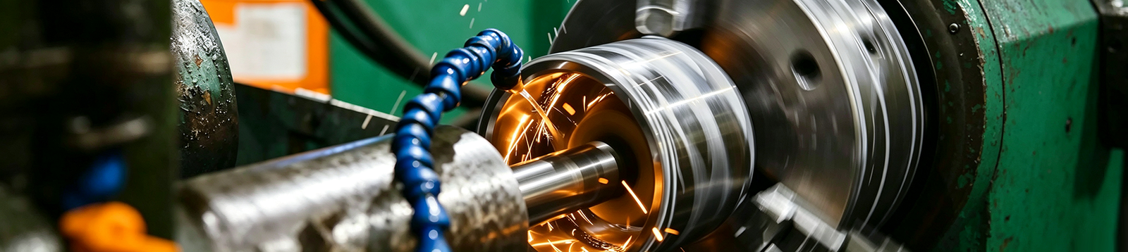
Grinding machining uses a bonded abrasive wheel to remove material at the micron level, producing dimensional accuracy and surface finish that milling and turning cannot reliably reach. It is primarily a finishing or final-sizing process — not a bulk-removal operation — and is especially relevant when parts require tight tolerances, low roughness, or machining of hardened materials.
When a part needs dimensional accuracy around ±0.001 mm, surface roughness below Ra 0.4 μm, or material hardness above HRC 45, conventional turning and milling often cannot hold the requirement consistently — this is when grinding becomes the right choice. This guide follows a single decision mainline: first decide whether grinding is needed, then choose the grinding type by geometry and volume, then fix allowance / datum / wheel / heat control / acceptance, and finally evaluate cost. The goal is to help engineers and buyers make defensible decisions at the design and quoting stage, not to pile up definitions.
Ⅰ. What Is Grinding Machining?
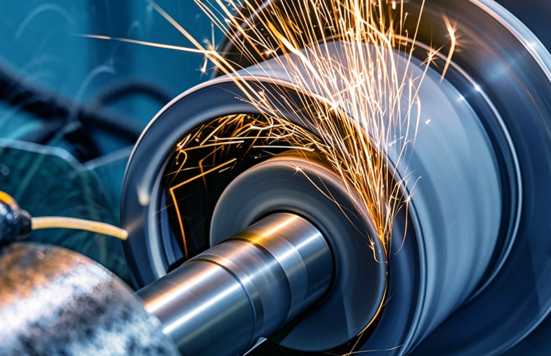
Grinding machining (also called abrasive machining) removes material using a high-speed rotating wheel whose surface carries thousands of abrasive grains. Each grain acts as a microscopic cutting edge, shearing off a very thin chip per pass. Because the uncut chip thickness is far smaller than in turning or milling, grinding achieves higher dimensional and geometric accuracy plus a markedly better surface finish.
Compared with milling and turning, grinding removes far less material per pass, so it is not competitive for roughing. Its real value appears on hardened steel, alloy steel, carbide and similar hard materials, where cutting tools wear too quickly — grinding is typically the final finishing operation after the bulk geometry has been rough-machined.
It is worth correcting a common assumption up front: grinding is not only a “low-efficiency finishing” process. Creep-feed grinding, high-efficiency deep grinding (HEDG) and high-volume centerless grinding can all achieve high material-removal rates or short cycle times, and they are covered separately below.
Ⅱ. When Do You Actually Need Grinding?
Not every part needs grinding. For most parts with wide tolerances, milling or turning already meets the requirement. Grinding becomes the right choice only when the part pushes harder on dimensional accuracy, surface finish or material hardness. Use the table below to decide quickly.
| Requirement | Need Grinding? | Alternative |
|---|---|---|
| Tolerance ±0.001–0.01 mm | Usually yes | Precision turning, lapping |
| Surface roughness Ra < 0.4 μm | Usually yes | Precision turning (material/structure dependent) |
| Material hardness > 45 HRC | Prefer grinding | Hard turning, EDM (for specific geometries) |
| Tolerance ±0.05 mm | Usually no | CNC milling or turning |
| High-volume simple OD | Centerless grinding fits | High-precision turning |
The core question is not “the higher the accuracy the better” — it is “does this feature actually need grinding to be held reliably?” A frequent mistake is to specify grinding on every surface; this raises cost and lead time without adding any functional value.
Grinding vs Milling vs Turning
Before diving into grinding types, it helps to frame how grinding differs from milling and turning — this keeps the selection logic grounded in mechanism rather than habit.
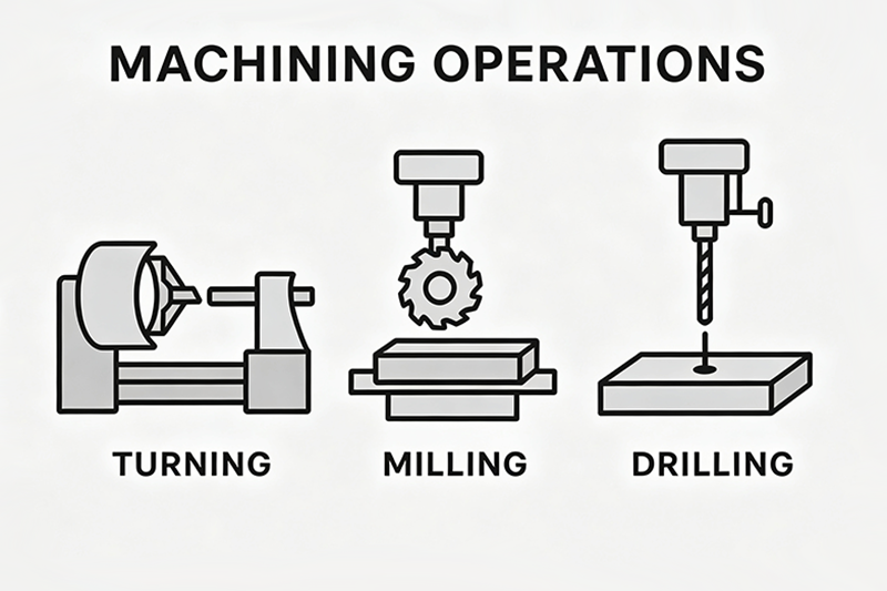
Grinding, turning and milling differ fundamentally in mechanism and accuracy. Grinding uses micro-cutting by abrasive grains — a finishing process for high accuracy and surface finish, typically the final operation on hardened steel or precision mating faces. Turning rotates the workpiece and feeds a single-point tool — efficient for OD/end-face of shaft-type parts. Milling rotates a multi-edge cutter while the workpiece or tool feeds — the most flexible, for flat surfaces, slots, cavities and complex 3D structures.
| Process | Typical Use | Common Parts |
|---|---|---|
| Grinding | Finishing, final sizing, high-precision mating faces | Bearing seats, precision shafts, mold working faces, hardened parts |
| Turning | Rough/semi-finish of shaft-type parts, cylindrical forming | Shafts, sleeves, discs, flanges |
| Milling | Flat surfaces, slots, cavities, complex 3D structures | Housings, structural parts, mold cavities, connectors |
No process is absolutely superior. Selection depends on part structure, tolerance, material and cost. Grinding is the high-precision finisher; turning suits rotational parts; milling fits flat, cavity and complex geometry. In practice they combine — a precision shaft is often turned to rough the diameter, milled for a keyway or cross-hole, then cylindrical-ground for the final bearing fit.
Ⅲ. Common Grinding Types
Grinding is classified by how the wheel contacts the workpiece. Different types fit different geometries, materials and batch sizes. The table below compares six mainstream types.
| Grinding Type | Best For | Typical Accuracy | Efficiency | Batch Size |
|---|---|---|---|---|
| Surface grinding | Flat faces, datum surfaces | ±0.002 mm | Medium | Low to medium |
| Cylindrical grinding | OD of shaft-like parts | ±0.001 mm | Medium | Low to medium |
| Internal grinding | Precision holes, ID surfaces | ±0.002 mm | Lower | Low |
| Centerless grinding | High-volume pins, slender shafts | ±0.001 mm | High | High volume |
| Creep-feed grinding | Deep slots, complex profiles | ±0.005 mm | High (deep cut) | Medium to high |
| HEDG (high-efficiency deep grinding) | Large stock removal on hard materials | ±0.01 mm | Very high | High volume |
Surface Grinding Uses the periphery or face of the wheel to machine flat workpieces for high-precision planes and low roughness. – Use: mold datum faces, precision fixtures, flat mating surfaces – Strength: flatness to 0.002 mm, roughness Ra 0.2–0.4 μm – Limit: flat surfaces only, medium efficiency
Cylindrical Grinding The workpiece rotates while the wheel feeds radially or axially to grind the OD. – Use: motor shafts, drive shafts, precision lead screws – Strength: roundness 0.001–0.005 mm, roughness Ra 0.1–0.4 μm, good concentricity – Limit: needs centers or chuck; slender parts are stiffness-limited
Internal Grinding The wheel enters the bore to grind the ID and internal cylindrical surfaces. – Use: bearing inner races, sleeves, precision bores – Strength: holes down to Ø3 mm – Limit: weak spindle rigidity, lower efficiency, deep holes are difficult
Centerless Grinding The workpiece is supported between a grinding wheel, a regulating wheel and a support blade — no centers or chuck needed — enabling continuous grinding. – Use: high-volume pins, piston rods, dowels and slender shafts, commonly Ø1–Ø150 mm (specialty machines extend the range below Ø1 or above Ø150) – Strength: high throughput (tens of parts per minute), consistent size, accuracy ±0.001 mm, easy to automate – Limit: mainly for continuous cylindrical surfaces; flanges, steps and special shapes are difficult
Creep-Feed Grinding A process using large depth of cut and low feed. Single-pass depth can reach 1–30 mm. – Use: aero-engine blade roots, turbine disk fir-tree slots, complex profiles in superalloys – Strength: forms deep slots or complex profiles in one pass, removing multiple milling and grinding steps – Limit: demands high machine stiffness, wheel performance and coolant capability; higher equipment investment
HEDG – High-Efficiency Deep Grinding Combines large depth of cut with high wheel surface speed. Depth is typically 1–30 mm; wheel speed reaches 80–200 m/s; material-removal rate is significantly higher than conventional grinding. – Use: aero-engine parts, hard materials, high-removal-rate batch work – Strength: removal rate approaching milling while retaining grinding-class accuracy and surface finish – Limit: usually needs CBN wheels, a dedicated high-stiffness machine and high-performance coolant; high equipment and process cost
Beyond the six above, several specialized grinding processes are common in high-volume or high-precision feature work:
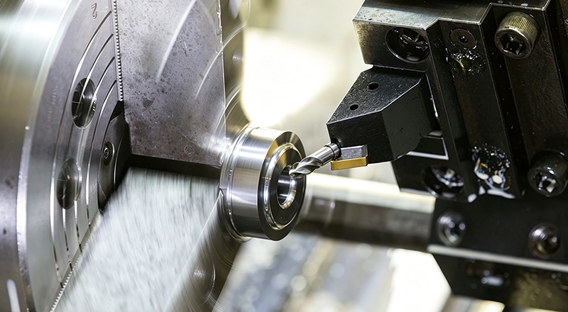
Form Grinding — the wheel is dressed to a specific profile that forms gear teeth, arcs or special slots in a single pass, making it efficient for gears, splines and precision cavities.
Gear Grinding — a dedicated process for finishing gear tooth flanks after heat treatment, using profile or generating methods. It is standard in automotive and aerospace transmissions where gear accuracy and noise control are critical.
Thread Grinding — produces precision threads on hardened parts such as ball screws, taps and lead screws, where post-hardness threading is otherwise impractical. It holds tighter pitch and profile tolerance than thread cutting or rolling on hardened stock.
Ⅳ. Grinding Precision Capabilities
Grinding is widely used in automotive, aerospace, medical, mold-making and precision machinery. But “how precise can grinding be” is not a single number — it depends on grinding type, part size, machine stiffness and inspection conditions. The table ties typical ranges to their applicable conditions, so the numbers are not quoted out of context.
| Item | Typical Range | Applicable Conditions & Notes |
|---|---|---|
| Dimensional accuracy | ±0.001 to ±0.01 mm | OD/centerless grinding in a temperature-controlled shop with two-center support reaches ±0.001–0.003 mm; large or long shafts are typically ±0.005–0.01 mm due to thermal and stiffness effects |
| Surface roughness Ra | Ra 0.02 to 0.8 μm | Ra 0.02–0.1 μm needs finish grinding + lapping/polishing with a uniform workpiece material; Ra 0.2–0.4 μm is standard finish grinding; Ra 0.4–0.8 μm is semi-finish |
| Roundness | 0.001 to 0.005 mm | OD/centerless grinding on Ø10–50 mm small/medium shafts reaches 0.001 mm; large-diameter or length-to-diameter > 5 slender parts are typically 0.003–0.005 mm |
| Cylindricity | 0.002 to 0.01 mm | Needs two-center or steady-rest support; thin-wall or deep-hole parts trend to the upper end due to deformation |
| Flatness | 0.002 to 0.02 mm | Surface grinding of small parts (< 200 mm) reaches 0.002–0.005 mm; large or thin plates are typically 0.01–0.02 mm due to thermal deformation |
| Concentricity | 0.002 to 0.01 mm | Grinding two ODs in one setup reaches 0.002 mm; second-setup work depends on datum alignment, typically 0.005–0.01 mm |
| Hole accuracy | ±0.002 to ±0.01 mm | Internal grinding of Ø3–50 mm bores reaches ±0.002–0.005 mm; deep holes or L/D > 3 are typically ±0.005–0.01 mm due to spindle rigidity |
Inspection conditions matter as much as the numbers: roundness and flatness should be measured in a temperature-controlled environment (20 ± 2 °C) with a dial indicator or roundness machine; roughness should be sampled along the lay with a roughness tester; dimensional accuracy must state whether it was measured by trial-cut or in-position grinding. Quoting precision without inspection conditions is a leading cause of drawing-versus-part disputes.
Ⅴ. Grinding Process Planning: Allowance, Datum, Wheel & Heat Control
Once you have decided grinding is needed and picked the type, the heart of process planning is to chain allowance, datum, wheel, heat control and acceptance into one executable mainline. These items determine whether the part can be held consistently and directly drive rework rate and cost.
Grinding Allowance Too much allowance lengthens grinding time and increases wheel wear; too little may not clean up prior deformation or surface defects. Typical recommendations: – OD grinding: 0.1–0.3 mm on diameter (quenched parts trend to the upper end to remove heat-treat distortion) – Surface grinding: 0.05–0.2 mm per side – Internal grinding: 0.05–0.15 mm on diameter – HEDG / creep-feed: 0.5–2 mm allowable, due to strong single-pass removal
Concrete values must combine prior-process stability (how much the turning/milling stock varies), quench distortion and part rigidity — not a universal constant.
Machining Datum The datum directly determines whether concentricity and flatness can be met. Prefer “one setup, multiple features” to avoid second-setup error. When one setup is impossible, specify a unified measurement datum on the drawing. Shafts commonly use two center holes as the unified datum; hole-type parts use a finished bore with a mandrel.
Wheel Selection Wheel selection covers five dimensions: abrasive, grit, hardness, bond and structure. Basic rules: – Hardened steel, alloy steel: white aluminum oxide (WA) or CBN – Carbide, ceramics: diamond (D) – Cast iron, non-ferrous: silicon carbide (C/GC) – Roughing: 46–60 grit; finish: 80–120 grit; mirror: 600–1200 grit (or FEPA F600–F1200)
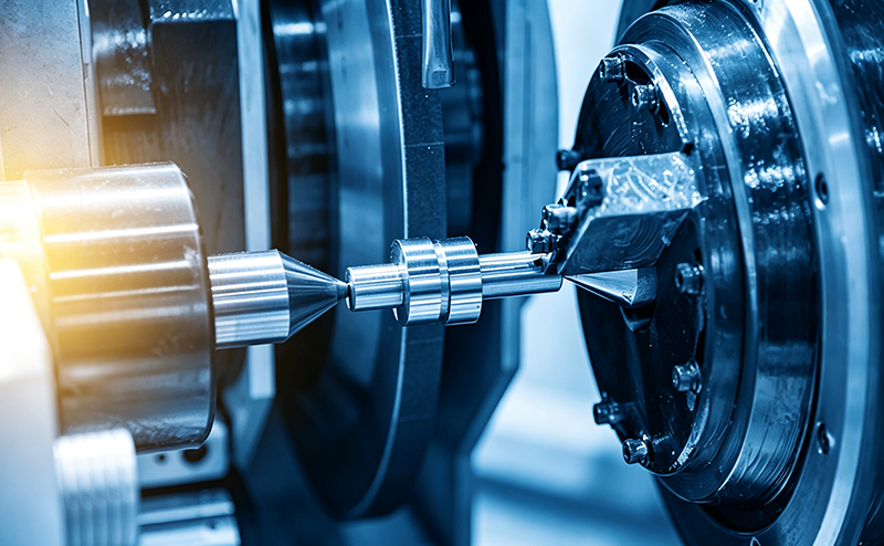
A useful concept here is the G-ratio — the volume of material removed divided by the volume of wheel wear. It is the core indicator of wheel life: a higher G-ratio means lower wheel cost per part. CBN wheels on hardened steel typically achieve far higher G-ratios than aluminum oxide, which is one reason superabrasives lower per-part cost despite higher wheel price. Soft material → hard wheel, hard material → soft wheel — this is the rule beginners most often reverse. “Wheel hardness” means the bond’s holding strength on the grain, not the hardness of the abrasive itself.
Heat Control Grinding heat is the main source of burn and cracking. Controls include: high-pressure coolant (0.5–2 MPa for normal grinding, up to 7 MPa+ for HEDG), sensible cutting parameters (avoid large depth + high feed combined), and timely wheel dressing to maintain self-sharpening. Low-thermal-conductivity materials such as stainless steel and titanium are especially heat-sensitive; use staged grinding (rough → semi-finish → finish) to step down allowance when needed.
Acceptance Requirements State on the drawing explicitly: dimensional tolerance, geometric tolerance (roundness / flatness / concentricity), surface roughness Ra and measurement direction, inspection method (dial indicator / roundness machine / CMM) and sampling conditions. Writing only “grind Ra 0.4” without datum or method is a high-frequency dispute point between buyer and supplier.
Ⅵ. Key Factors Affecting Grinding Quality
Grinding quality is set by multiple variables — wheel, parameters, coolant, machine, workholding and material. As an engineer or buyer you do not tune these parameters yourself, but understanding them lets you judge whether a supplier can control quality consistently. The table below is organized by what to ask the supplier.
| Category | Factor | Effect on Quality | What to Ask the Supplier |
|---|---|---|---|
| Wheel | Grit size | Directly drives roughness and removal rate | What grit size will you use to hit my Ra requirement? |
| Wheel | Hardness & abrasive type | Affects burn, wear and wheel life | What abrasive — CBN, diamond or aluminum oxide — and why? |
| Wheel | Dressing state | Affects stability, size consistency and finish | How do you set the dressing interval? Do you keep dressing logs? |
| Parameters | Wheel speed & feed | Affects efficiency, finish and grinding temperature | Are parameters set by experience, or verified by trial grinding? |
| Parameters | Depth of cut & allowance | Affects accuracy, efficiency and thermal deformation | How much grinding allowance will this part carry, and on what basis? |
| Coolant | Type, pressure & filtration | Affects burn, chip evacuation and finish | Do you run high-pressure coolant with filtration? |
| Machine | Stiffness & vibration | Affects size, waviness and stability | What grinder model? Do you monitor vibration or check it periodically? |
| Machine | Spindle accuracy | Affects roundness, concentricity and finish | What is the spindle accuracy? How often is it verified or calibrated? |
| Workholding | Method & rigidity | Affects deformation, concentricity and repeatability | For this slender or thin-wall part, what workholding do you use? |
| Material | Hardness & thermal conductivity | Affects wheel choice, difficulty and burn risk | Have you ground this material before? Can you share process records from a similar job? |
Red flags: if a supplier answers vaguely, stressing only “rich experience” without being able to specify wheel type, parameters, dressing interval or inspection method — or refusing to share process records — this usually means their process control is insufficient for stable precision grinding. A capable supplier should be able to answer each question above with traceable data: wheel spec sheets, dressing logs, parameter sheets and inspection reports.
Ⅶ. Advantages & Limitations
Advantages – High accuracy: micron-level dimensional control (±0.001–0.01 mm), tighter than conventional milling/turning – High surface quality: Ra 0.02–0.8 μm, mirror-class possible at the low end – Hard-material capability: works on HRC 45–70 hardened steel, carbide, ceramics – Consistency: stable per-part accuracy in volume, suited to high-interchangeability parts – High-efficiency grinding: creep-feed and HEDG enable high removal rates where applicable
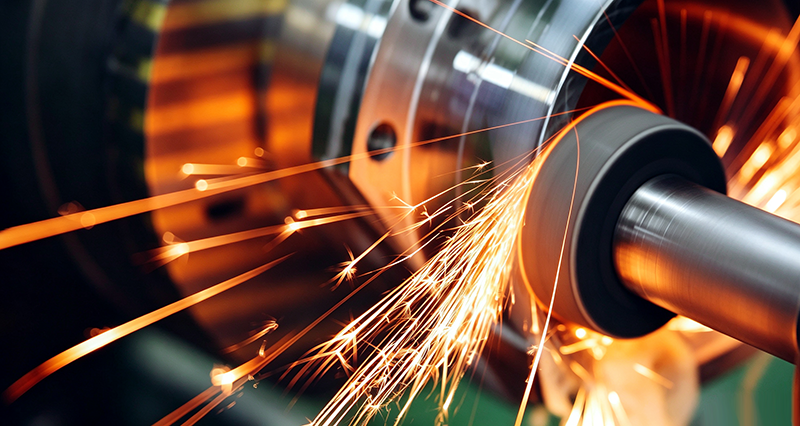
Limitations Material-removal efficiency is lower than rough milling/turning, so grinding is unsuitable for large-stock roughing. The process is sensitive to wheel, coolant and parameters — poor control leads to burn, vibration or surface defects. Equipment and process cost are relatively high, and operator experience and process discipline are demanding, so grinding is normally used as a finishing or final-sizing step. Creep-feed and HEDG have broken the “grinding = slow” assumption — in specific scenarios their removal rate can approach milling.
Ⅷ. Common Defects and Root-Cause Solutions
Even with good equipment and a mature process, quality can drop due to bad parameters, wheel condition or insufficient coolant. The table below does not just give countermeasures — it lists the judgment order and applicable conditions, so you do not fall into simplistic fixes like “burn → reduce feed” that can actually make the problem worse.
| Problem | Main Causes | Judgment Order & Solution |
|---|---|---|
| Surface burn | Excessive feed / insufficient coolant / wheel too hard / depth too large | First locate the burn: at the end only = entry impact, reduce depth or add a chamfer; along the full length = coolant or wheel issue. Order: ① check coolant nozzle angle and flow (is the air layer deflecting it?) → ② reduce per-pass depth, add spark-out passes → ③ drop one wheel grade or choose a more open structure → ④ only then consider reducing feed, because simply lowering feed extends contact time and can worsen heat accumulation |
| Rough surface | Grit too coarse / dulling / vibration / insufficient spark-out | Dress the wheel first to rule out dulling. If still rough, distinguish texture roughness from chatter marks: texture → drop 1–2 grit grades; chatter → check machine vibration and wheel balance, do not just change the wheel. Add 2–3 spark-out passes at the end to cut Ra significantly |
| Dimensional instability | Wheel wear / thermal deformation / parameter drift / clamping loose | Measure first-to-last part spread: first part good but last out of tolerance = wheel wear, shorten dressing interval; random within batch = check workholding and parameter stability. Thermal drift shows as size shifting after the cut — let the part cool, then re-measure, and control coolant temperature |
| Chatter / waviness | Machine vibration / wheel unbalance / spindle clearance / critical-speed resonance | Do not just balance the wheel. First check whether the chatter frequency is an integer multiple of wheel speed — if yes, look at wheel balance and dressing; if no, check spindle bearing clearance and foundation isolation. Critical-speed resonance needs the wheel speed moved out of the resonance band |
| Workpiece deformation | Over-clamping / poor rigidity / grinding heat / stress release | Thin-wall parts prefer collets or magnetic chucks with distributed force, not three-jaw chucks; slender shafts use steady rests. Quenched-part deformation often comes from internal stress release — stage the process (rough → semi-finish → finish) with stress-release time between stages |
| Wheel loading | Poor chip evacuation / material adhesion / wheel too hard or too closed | First distinguish “loading” (chips in pores) from “dulling” (grain flat). Loading: switch to a more open structure, increase coolant flush, reduce wheel hardness. Dulling: shorten dressing interval, pick a more self-sharpening abrasive. Non-ferrous and rubber-like materials load easily — use silicon carbide and lower surface speed |
| Excessive wheel wear | Wrong wheel / aggressive parameters / material too hard | Fast wear — first check abrasive choice (e.g., aluminum oxide on carbide). Glassy wheel face = parameters too aggressive; reduce depth and feed. For very hard materials, switch to CBN or diamond |
| ID size deviation | Wheel wear / weak spindle / taper | Deep-hole taper = spindle deflection; reduce wheel overhang and depth. Bell-mouth at entry = entry impact; add a guide chamfer. Internal grinding needs more frequent dressing than OD |
Ⅸ. Grinding Cost Evaluation & Optimization
Grinding usually costs more than milling or turning per hour because efficiency is lower and the process demands precision equipment, abrasive tooling and strict inspection. However, for high-precision, high-finish or hard-material parts, grinding reduces rework and assembly issues, so the total manufacturing cost can still be favorable.
| Cost Driver | Impact | How to Optimize |
|---|---|---|
| Material hardness | ★★★★ | Pick the right wheel; optimize parameters |
| Grinding allowance | ★★★★★ | Leave only a small finish allowance after roughing |
| Tolerance requirement | ★★★★★ | Specify ultra-precision only on critical dimensions |
| Surface roughness | ★★★★ | Do not over-specify finish |
| Geometric complexity | ★★★★ | Simplify the design; cut special grinding steps |
| Batch size | ★★★ | Volume lowers per-part cost |
Grinding cost is not set by cycle time alone — part design, material and tolerance all feed in.
How to reduce grinding cost – Control allowance: rough most of the stock in turning/milling, leaving only a finish allowance, to shorten grinding time. – Match the wheel to material and requirement; optimize parameters to raise feed within finish limits, cutting unnecessary finish passes and dressing cycles. – Coolant matters: good lubrication lowers grinding temperature, reducing burn, thermal deformation and wheel loading, extending wheel life. – Keep machine stiffness and workholding stable to cut vibration and clamping error, avoiding rework from out-of-tolerance or surface defects. – At the planning stage, do not grind every surface — grind only critical dimensions, mating faces and high-finish areas; use turning or milling for the rest.
Ⅹ. Grinding Design Checklist
Good design raises grinding efficiency and lowers difficulty and cost. Thinking through allowance, tolerance, material and workholding at the design stage yields more stable quality and lower scrap. Use this checklist as a reference for part design and process review.
| Check Item | Design Requirement | Pass? |
|---|---|---|
| Allowance | Is a sensible grinding allowance reserved (see Process Planning section for per-type values)? | |
| Tolerance | Are dimensional tolerances explicit (μm / IT grade)? | |
| Surface roughness | Is Ra defined (e.g., Ra 0.2–0.8 μm)? | |
| Material state | Is it hardened or grindable? | |
| Feature accessibility | Can the wheel reach the grinding zone? | |
| Workholding | Is stable clamping feasible? | |
| Datum | Is the machining datum explicit? | |
| Shape limits | Are overly complex curves or sharp corners avoided? | |
| Thermal control | Is grinding heat accounted for? | |
| Allowance uniformity | Is the allowance evenly distributed? | |
| Wheel clearance | Are wheel size and interference considered? | |
| Batch consistency | Does it meet batch repeatability? |
XI. Conclusion
The core value of grinding machining is the combination of high accuracy and high surface finish, especially for the final machining of hardened steel, tool steel and other hard materials. Its removal efficiency is lower than rough machining and its cost is higher, and it demands tight control over wheel selection, parameters, coolant and machine stability. Plan the route so grinding concentrates on critical mating faces or final finishing, controlling cost while holding quality.
If you are in part design or process planning, run the checklist above first to see if any grinding callout is over-specified — much of the cost can be cut through process optimization. Keywin can help you sort which features truly need grinding and which can be shifted to turning or milling, preserving function while lowering total cost. Get a quote for CNC machined parts with grinding or request a DFM review for your grinding features, and we will walk you through the most cost-effective route.
FAQ
Q: Is grinding always more accurate than milling?
A: Not always. Grinding typically reaches higher accuracy and lower roughness than milling, but a high-stiffness milling machine with finishing tooling can also reach respectable accuracy. Final accuracy depends on material, machine stiffness, parameters and the machining stage — not on the process label alone.
Q: What materials can grinding handle?
A: A wide range, especially hardened steel, tool steel, alloy steel and carbide, plus cast iron, copper, aluminum and some engineering plastics. Each material needs the right wheel and parameters to avoid burn, loading or burrs.
Q: How is grinding priced?
A: Usually higher per hour than turning or milling, due to lower efficiency, higher process demands and wheel consumption. Price is driven by tolerance, material hardness, cycle time and surface roughness. Precision grinding or hard-material work costs more; plain surface grinding is relatively low.
Q: At which stage is grinding done?
A: Usually at the end of the route, as a finishing or final-sizing step to correct size, raise accuracy and lower roughness. It follows turning or milling rough/semi-finish, and is used for high-precision mating faces and the final shaping of hardened materials.
Q: How can I reduce grinding cost?
A: The keys are shortening cycle time and cutting wheel loss. Control allowance, optimize feed and parameters, avoid over-specifying finish, and replace grinding with turning/milling on non-critical faces. Choose the right wheel, improve coolant efficiency, cut dressing cycles and stabilize workholding to lower rework.
Q: How much grinding allowance should I leave?
A: Typical values: OD grinding 0.1–0.3 mm on diameter, surface grinding 0.05–0.2 mm per side, internal grinding 0.05–0.15 mm on diameter. Quenched parts trend to the upper end for heat-treat distortion; HEDG and creep-feed can run 0.5–2 mm because of strong single-pass removal. Concrete values combine prior-process stability, material distortion and part rigidity — not a fixed constant.