
Radial grooving is a common turning operation used to create circular grooves on the external or internal surfaces of cylindrical parts. These grooves are typically used to accommodate O-rings, retaining rings, or provide clearance for threading and assembly.
Although radial grooves may appear simple on engineering drawings, their dimensions and positioning can significantly affect machining performance. Groove width, depth, corner radii, and location all influence tool selection, cutting stability, and dimensional accuracy. Narrow or deep grooves can also present challenges such as poor chip evacuation, tool deflection, and vibration.
This article explores how radial grooving works, its main types, tooling considerations, and key factors for achieving accurate and consistent results.
Ⅰ. What Is Radial Grooving?
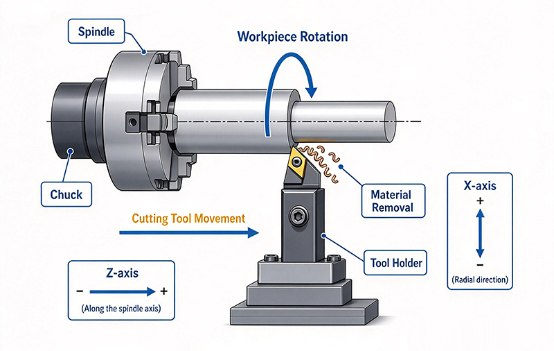
Radial grooving is typically performed on a lathe or turning center. During machining, the workpiece rotates while a grooving tool feeds radially toward the rotational axis, removing material to form a groove of the required width and depth.
The groove width is generally determined by the cutting insert width, while the groove depth is controlled by the radial feed distance. If the required groove is wider than the insert, multiple cutting passes or axial tool movements can be used to achieve the desired dimensions.
Radial grooving is mainly divided into two types based on the groove location:
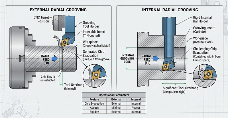
- External Radial Grooving: Creates circular grooves on the outer diameter of a workpiece, commonly used for retaining ring grooves and sealing grooves.
- Internal Radial Grooving: Produces grooves inside a bore using specialized internal grooving tools, often for internal seals or retaining rings.
Radial grooving is similar to parting off in terms of tool movement, but the machining objectives differ. Radial grooving creates a recessed feature on the workpiece surface, whereas parting off involves feeding the cutting tool toward the rotational center until the part is separated from the bar stock.
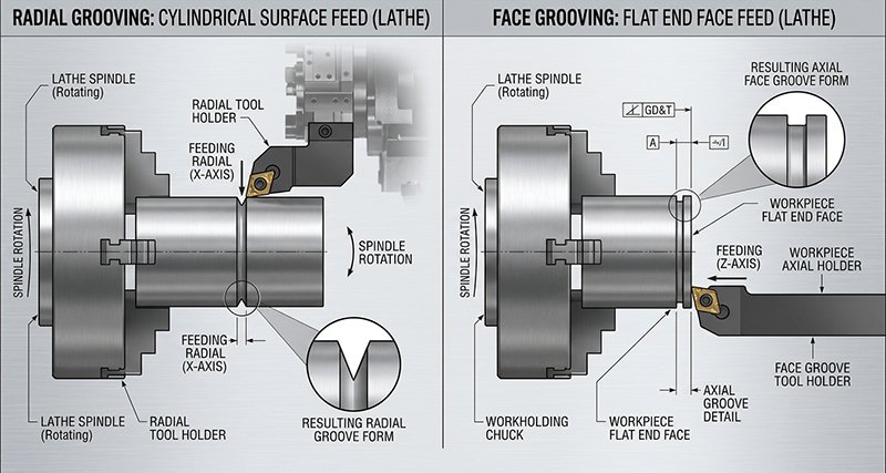
It also differs from face grooving. Radial grooving produces circular grooves on cylindrical surfaces, while face grooving creates annular grooves on the flat end face of a workpiece, typically using an axial feed direction.
Ⅱ. How Does the Radial Grooving Process Work?
CNC radial grooving runs on the same lathes as general CNC turning work, and cutting data changes with material, insert, and machine — so the steps below describe decisions rather than speeds and feeds. Keywin’s CNC turning services cover groove features and surrounding turned geometry.
1. Review the Groove Drawing
Before machining, confirm whether the job is external radial grooving or internal radial grooving, then check the drawing’s key requirements: groove width, depth or bottom diameter, position, bottom corner radius, side-wall shape, tolerance, and surface finish. Depth and locating dimensions need particular attention — without them, wall thickness is undefined and the groove can land in the wrong place.
2. Select the Tool and Insert
Select the radial grooving tool and insert from groove width, depth, workpiece material, and groove location, then confirm insert width, corner radius, and tool rigidity against the drawing. Internal work adds bore diameter, groove position, and bar overhang — longer overhang means lower rigidity, more vibration, and less accuracy.
3. Set the Tool Center Height
The grooving tool must sit on the workpiece’s rotational center, mounted square and clamped firmly. Center height too high or too low changes the cutting conditions, hurts bottom quality, and raises the risk of tool wear and vibration. A crooked or loosely clamped tool also shifts groove width, side-wall shape, and surface quality.
4. Cut the Groove
Three approaches cover most work, chosen by groove width, depth, and accuracy requirements:
• Single plunge — one radial feed to target depth, for narrow, shallow grooves.
• Multiple plunges — stepping the tool axially and plunging more than once, when the groove is wider than the insert.
• Roughing and finishing — leaving an allowance, then finishing the bottom and side walls where tolerance or finish is tighter.
Which applies depends on part structure and quality requirements, and the approaches can be combined: a shallow external relief groove may be done in one plunge, a precision internal seal groove cannot.
5. Inspect the Finished Groove
After machining, check groove width, depth or bottom diameter, position, bottom corner radius, side-wall shape, and surface finish against the drawing, and confirm no burrs at the groove mouth. Deep or narrow internal grooves may be out of reach for ordinary calipers, so inspection may need a groove gauge or bore measuring tool. Decide the inspection method before machining — the groove has to be measurable, not just machinable.
Ⅲ. External vs Internal Radial Grooving
Radial grooving usually brings external grooves to mind, but it applies to bores as well. Both feed radially; the difference lies in the space available, the tool selection, and the cutting and chip evacuation conditions.
| Factor | External radial grooving | Internal radial grooving |
|---|---|---|
| Cutting location | Outside diameter | Inside a bore |
| Tool access | Usually more open | Restricted by bore diameter and depth |
| Chip evacuation | Generally easier | More difficult |
| Rigidity | Usually higher | Reduced by bar overhang |
| Inspection | More accessible | May require bore or groove gauges |
| Common uses | O-ring, snap-ring and relief grooves | Internal seal, retaining-ring and relief grooves |
Internal work concentrates difficulty in four places: the cut cannot be seen, the bar must reach it, chips must clear past the bar, and measurement access is limited. Evacuation is underestimated — a chip that cannot clear gets recut and breaks the insert.
Ⅳ. Radial Grooving vs Face Grooving
The difference between radial grooving and face grooving goes beyond feed direction: it also covers where the groove is cut and the tool used. Radial grooving cuts on an outside diameter or inside a bore; face grooving cuts a circular groove on the flat end face of the part.
| Feature | Radial Grooving | Face Grooving |
|---|---|---|
| Tool-feed direction | Toward the rotation axis | Axial, into the part face |
| Groove location | OD or ID cylindrical surface | Front face of the part |
| Resulting groove | Circumferential groove | Circular face groove |
| Holder geometry | Straighter support structure | Curved or relieved support often needed |
| Main design concern | Width, depth, wall geometry, radial access | Groove diameter range and holder clearance |
And because groove diameter changes as the tool feeds in, the usable diameter range is a tooling constraint, not a free choice.
Ⅴ. Common Applications of Radial Grooving
O-Ring and Seal Grooves
Radial grooving cuts the seats for O-rings and other seals. Width, depth, and surface quality decide how the seal sits and how well it seals — wrong width changes its location and room to deform, wrong depth leaves compression too low or too high, and defects on the bottom or side walls affect sealing too. Design to the specification covering the seal type, working pressure, and service conditions.
Retaining-Ring and Snap-Ring Grooves
A retaining-ring groove holds a circlip or snap ring that limits axial movement on a shaft or in a bore. Width, depth, position, and side-wall quality decide whether the ring seats and carries load. The walls take the axial load, so their dimensions and strength have to match. Groove dimensions come from the ring type, size, and applicable standard.
Thread Relief Grooves
A thread relief is machined at the end of a thread to give the threading tool the runout it needs, so it clears an adjacent shoulder instead of interfering with it. It also lets the thread form a full profile close to that shoulder. The relief changes the local section, so on parts under high or cyclic loads, depth and bottom radius need to be chosen with stress concentration in mind.
Bearing and Assembly Reliefs
Bearing and assembly reliefs prevent geometric interference so a bearing or mating part seats fully against a shoulder. A relief at the shoulder root leaves room for the chamfer or radius on the adjacent part, which would otherwise disturb assembly location. What controls here is groove position, depth, and the relationship to the adjacent mating surface — not sealing.
Parting-Off: A Related Operation
Parting off and radial grooving both feed the tool radially, but the purpose is different.
• Radial grooving — forms a groove of specified width and depth while the workpiece stays intact.
• Parting off — keeps feeding the tool toward the center of rotation until the part separates from the bar.
The two operations may run on similar inserts and tool systems, but tool selection, cutting parameters, and chip evacuation requirements are not necessarily the same. Parting off reaches deeper, so tool rigidity, chip control, and cooling need particular attention.
Ⅵ. Radial Groove Design Guidelines
The groove itself is usually simple; the problems come from what the drawing does not say.
Specify Width, Depth, and Position Clearly
A note reading only “groove” cannot be quoted or inspected. Give nominal width and tolerance, location from a datum or shoulder, and radial depth or bottom diameter — plus which dimension controls the remaining wall where load crosses it.
Define the Bottom and Corner Geometry
Inserts carry corner radii, so a sharp internal corner is not a default outcome — specify the maximum bottom radius. A very small radius combined with a deep narrow groove removes tool options and raises cost.
Check Tool Access
Look at what sits next to the groove: a nearby shoulder, small bore, deep hole, adjacent boss, or high depth-to-width ratio. Each constrains holder size and overhang — and those two decide whether the operation stays stable.
Avoid Unnecessarily Tight Tolerances
Apply width, position, and bottom-diameter tolerances where function needs them and leave the rest general. Surface finish belongs where friction or sealing depends on it, not across the whole groove. Tighter callouts cost more to make and verify.
Consider Burr Removal and Inspection
Decide how the burr is removed and the groove measured before the design is final — a narrow internal groove is hard to deburr and see, and a feature nobody can inspect cannot be accepted reliably.
| Drawing item | Specify | Why it matters |
|---|---|---|
| Groove location | Datum or shoulder reference | Controls assembly position |
| Width | Nominal width and tolerance | Affects seal or ring fit |
| Depth | Radial depth or bottom diameter | Controls function and remaining wall |
| Corner radius | Maximum allowable radius | Determines tool and insert geometry |
| Surface finish | Only where function requires | Affects sealing and friction |
| Burr requirement | Critical edges and allowed condition | Affects assembly and cleanliness |
| Inspection method | Functional or dimensional requirement | Prevents ambiguous acceptance |
Ⅶ. Common Radial Grooving Problems and Their Causes
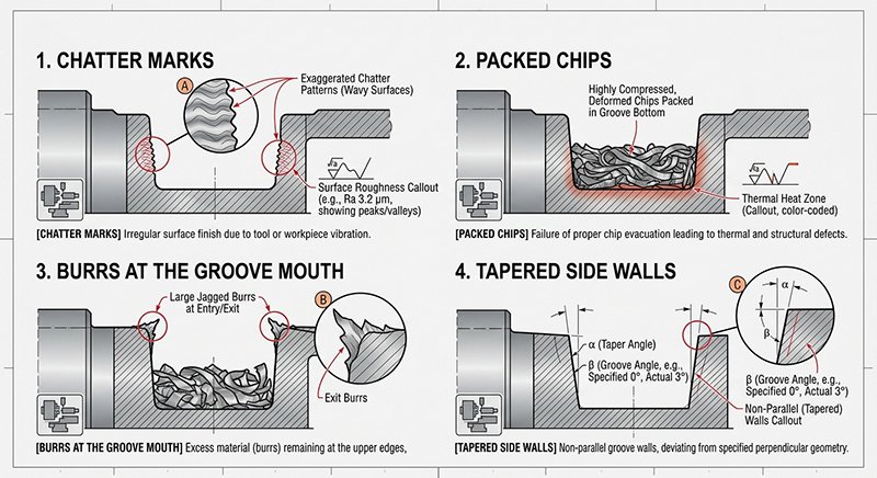
The causes below repeat across materials; which applies depends on part, setup, and radial grooving tool — no single fix suits every material.
| Problem | Likely causes | Engineering response |
|---|---|---|
| Chatter or vibration | Long overhang, weak setup, wide insert, poor rigidity | Shorten overhang, improve support, consider narrower cuts |
| Chip jamming | Deep groove, internal location, poor coolant access | Improve evacuation and coolant delivery; revise cut sequence |
| Groove width error | Tool alignment, insert wear, deflection | Check center height, tool condition, and finishing pass |
| Tapered side walls | Deflection or incorrect tool setup | Improve rigidity and alignment |
| Poor bottom finish | Built-up edge, vibration, unsuitable conditions | Review insert geometry, material, and cutting strategy |
| Burrs | Dull insert, material behavior, interrupted exit | Adjust tooling and specify deburring requirements |
| Insert breakage | Chip recutting, excessive load, unstable holder | Improve chip control, setup, and cut distribution |
Ⅷ. How Material Affects Radial Grooving
Material decides which problem surfaces first:
• Aluminum — long chips and built-up edge, depending on alloy and insert condition.
• Stainless steel — work hardening, heat, and chip control dominate.
• Carbon and alloy steel — tool load tracks hardness, so insert grade and geometry have to match.
• Brass and copper alloys — chip breaking and burr behavior vary by grade.
• Titanium — heat concentrates at the cut, making stable feed and wear management more important.
• Engineering plastics — deflection, melting, edge fuzzing, and dimensional recovery after machining.
None reduce to a universal table — cutting data is set per material, insert, and machine condition.
Ⅸ. What to Include in a Radial Grooving RFQ
Send the 3D CAD model, a dimensioned 2D drawing, material and condition, groove location, width and tolerance, depth or bottom diameter, corner radius, surface finish, burr and edge requirements, quantity, and inspection requirements.
If the groove interfaces with an O-ring, retaining ring, thread, or mating component, identify the applicable standard or the mating-part requirements — that line removes most guesswork between drawing and quote.
Ⅹ. Conclusion
Radial grooving produces a circumferential groove by feeding a narrow tool toward the rotational center of a rotating part, on an OD or in a bore. The result depends less on the machine than on the drawing: width, depth, position, tool access, chip control, rigidity, and material all move it.
Groove machining problems are frequently definition problems in disguise, so complete dimensions belong in the RFQ, not a clarification email.
Send Keywin your 3D model and dimensioned drawing for a manufacturability review of groove access, geometry, material, tolerances, and inspection requirements.
Frequently Asked Questions
1. What is radial grooving?
Radial grooving is a turning operation in which a narrow tool feeds toward the rotational center of a rotating workpiece, cutting a groove around its circumference. It can be external, on an OD, or internal, inside a bore.
2. What is the difference between radial grooving and face grooving?
Radial grooving feeds toward the rotational axis and cuts on a cylindrical OD or ID surface, producing a circumferential groove. Face grooving feeds axially into the flat end face and produces a circular face groove, generally needing different holder geometry.
3. Can radial grooving be used for internal grooves?
Yes — internal radial grooving applies the same radial feed inside a bore. The limits are access: bore diameter caps bar size, depth sets overhang, and chips must clear past the bar, so inspection may need bore or groove gauges.
4. Is parting-off a radial grooving operation?
It uses radial feed motion, but the intent differs: grooving leaves the part attached at a defined depth, while parting off continues to the center to separate it from the bar, and needs tooling designed for that feed.
5. What dimensions should be included on a radial groove drawing?
Nominal width and tolerance, location from a datum or shoulder, radial depth or bottom diameter, maximum bottom corner radius, and burr or edge requirements. Missing any lets the same drawing be produced two ways.
6. Why does a radial grooving tool chatter?
Usually rigidity: tool overhang — especially in deep bores — a weak setup, too wide an insert, incorrect center height, or a worn holder. Material and cutting conditions contribute, but support and overhang come first.