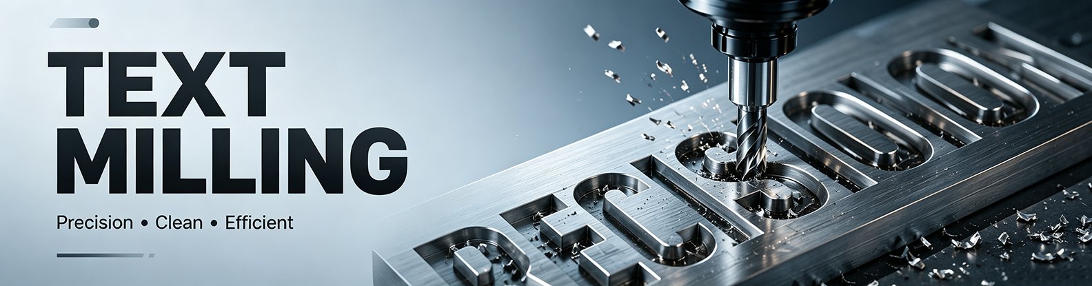
A designer might perfectly configure the logo engraving in CAD—with the typeface and spacing looking flawless—only to be told by the factory that the batch requires rework. The issue usually isn’t the aesthetics of the font itself, but rather strokes that are too fine or depth settings that lack precision, making it impossible for the cutting tool to reliably reproduce the design. While text milling may seem like a simple “engraving” task, a mismatch in any variable—typeface, line width, depth, or material—can lead to problems ranging from blurred text and burred edges to the need for rework or even the rejection of the entire batch of cosmetic parts. This article briefly explains the machining principles but focuses primarily on the critical choices that must be made during the design phase.
Ⅰ. What is Text Milling?
In CNC machining, “text milling” refers to a process in which a CNC milling machine uses a cutting tool to machine the surface of a workpiece—following a preset font outline or path—to create clear text, numbers, or symbols. This method is commonly used for surface marking on materials such as metal and plastic, producing elements like part numbers, product models, nameplate details, and brand logos. Depending on the specific machining approach, text milling can employ techniques such as contour milling, single-line font machining, or pocket milling to meet varying requirements for precision, depth, and visual appearance; it is one of the standard methods for marking in CNC machining.
The workflow from CAD to G-code for text milling consists of four steps: designing the text outline in CAD → exporting it as a vector file (DXF/SVG) → generating the toolpath using CAM software → outputting the G-code and machining. During the CAD phase, designers must ensure that fonts are converted into vector lines rather than bitmaps; otherwise, the CAM software will be unable to generate a machinable toolpath. DXF or SVG formats are recommended to preserve vector precision.
Text milling is a reliable CNC machining method to etch characters, serial codes and logos onto metal parts. Commonly adopted in automation, automotive and machinery manufacturing for component identification.
Ⅱ. When Should You Choose Text Milling?
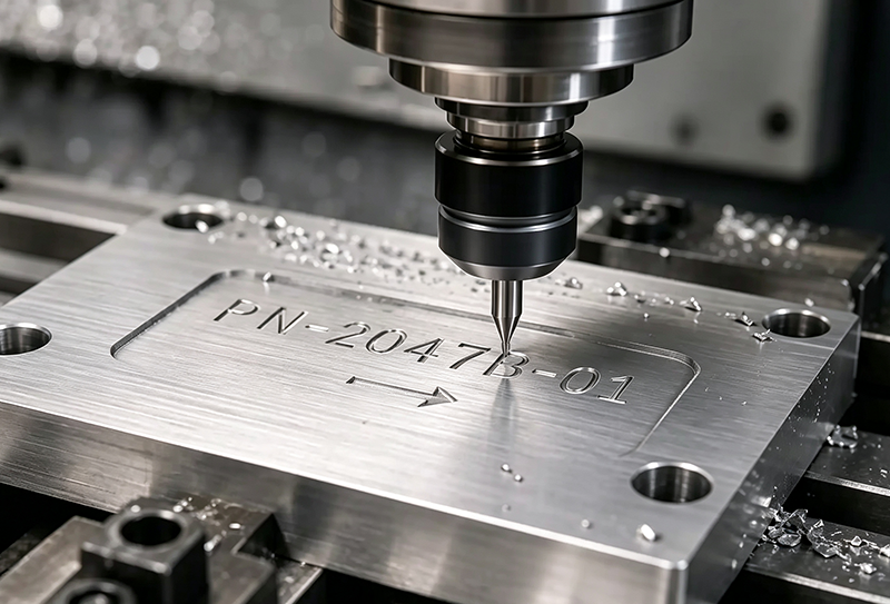
Text milling is better suited for applications that demand high levels of durability, reliability, and long-term readability for markings. Unlike surface printing or shallow marking, CNC milling creates permanent recesses by removing material, making the markings resistant to degradation from friction, cleaning, or environmental exposure. Consider the following criteria when making your choice:
Requirement for long-term wear and corrosion resistance → Prioritize Text Milling
For applications such as outdoor equipment, chemical processing equipment nameplates, and machinery part markings, shallow laser markings or ink-based labels may fade over time when exposed to rain, oil, or cleaning agents; milled text, however, remains legible for the long term.
Requirement for permanent traceability → Prioritize Text Milling
For items such as aerospace components, mold identification numbers, and industrial equipment serial numbers, clear identification must be maintained throughout the product’s lifecycle to prevent tracking difficulties caused by damaged markings.
Requirement for a premium appearance and mechanical aesthetic → Choose Text Milling
For precision equipment, aluminum housings, and high-end product components, the three-dimensional recesses created by milling offer a distinct machined-metal look; this can be further enhanced through processes such as sandblasting or anodizing.
For metal parts requiring significant depth and defined edges → Choose Text Milling
For metal components made of materials such as aluminum alloy, brass, or stainless steel, CNC milling/engraving achieves superior depth and edge definition, making it ideal for applications requiring crisp lettering and precise dimensions.
When Text Milling is not recommended
If production volumes are extremely high, markings change frequently, or only low-cost surface labeling is required, methods such as screen printing, labeling, or laser engraving are usually more economical. For instance, in scenarios like disposable packaging or mass-produced consumer electronics housings, CNC milling/engraving could incur unnecessary processing costs.
Ⅲ. Text Milling vs. Laser Engraving vs. Screen Printing vs. Labeling
CNC milling is not the only method for text marking; different processing techniques vary significantly in terms of cost, durability, machining depth, and suitability for specific applications. Depending on the product’s intended use, operating environment, and lifespan requirements, one can choose from options such as text milling, laser engraving, screen printing, or labeling. Below is a comparison of several common marking methods.
| Marking Method | Depth | Durability | Cost per Part | Compatible Materials | Processing Time |
|---|---|---|---|---|---|
| Text Milling | 0.2–1 mm, material is physically removed by CNC cutting tools | ★★★★★ | High | Metals, plastics, wood, and other machinable materials | Minutes to tens of minutes |
| Laser Engraving | 0.01–0.2 mm, material is removed or surface properties are altered using a laser beam | ★★★★ | Medium | Metals, plastics, glass, ceramics, and more | Seconds to minutes |
| Screen Printing | No depth, markings are formed by applying ink onto the surface | ★★ | Low | Plastics, metal panels, glass, and other smooth surfaces | Seconds to minutes |
| Labeling | No depth, information is attached using adhesive labels | ★ | Lowest | Most flat surfaces and materials | Seconds |
In terms of long-term use and reliability, physical processing methods generally offer superior wear resistance, whereas surface treatment methods are better suited for cost-sensitive, high-volume production scenarios. The final choice should take into account factors such as the material, operating environment, required lifespan of the markings, and production volume.
Ⅳ. Choosing the Right Text Milling Method
Selecting the machining method is a critical decision in Text Milling design, as different approaches significantly impact tooling, depth, font appearance, and cost. The following five methods cover the vast majority of application scenarios.
Single-Line Engraving
This method involves tracing the font’s centerline using a V-bit or a small-diameter end mill, completing the cut in a single pass. Advantages: fastest machining speed, simple programming, and suitability for small text. Disadvantages: stroke width is determined by the tool, preventing variation in line thickness. Suitable for: serial numbers, batch numbers, rapid marking, and small text (2–4 mm character height).
Achieve crisp, delicate lettering on metal parts using professional CNC text milling single-line engraving technology. Widely adopted in mold manufacturing, hardware accessories and mechanical component identification for permanent, readable markings.
Profile Milling
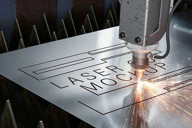
The tool follows the outer contour of the characters, resulting in crisp edges. Pros: High fidelity to character shape, clean edges, and maximum versatility. Cons: Slower than single-line milling; requires matching tool diameter to stroke width. Suitable for: Medium-sized characters (4–15mm), applications requiring sharp edges, and general industrial signage.
CNC profile milling delivers consistent contoured shapes on aluminum and steel workpieces. Widely adopted in precision machinery, automotive and automation parts production for tight tolerance finished profiles.
Pocket Milling
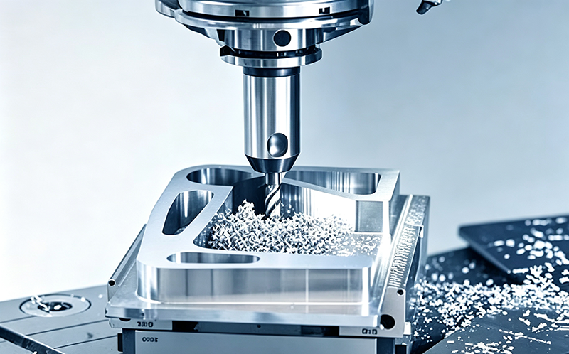
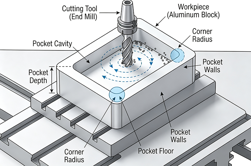
The interior of the character is hollowed out to create a deep, recessed effect. Pros: Significant depth, high contrast, and allows for color filling (e.g., black paint). Cons: Longest machining time and significant tool wear. Suitable for: Color-filled logos, high-contrast decorative elements, and deep lettering (>0.5mm depth).
CNC pocket milling is widely used in mechanical manufacturing to machine enclosed cavities in aluminum, steel and alloy materials. This process delivers consistent depth control and smooth inner surfaces for mold parts and automation components.
V-Carving
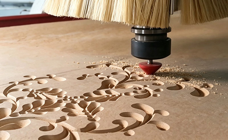
Uses a V-shaped tool, with stroke width varying according to carving depth. Pros: Strong decorative appeal, three-dimensional look, and a single tool can handle various line widths. Cons: Requires a specialized V-bit and high precision in depth control. Suitable for: Decorative fonts, calligraphic styles, and wood or plastic ornaments.
V-Carving is a popular text milling technique using V-shaped cutters to create crisp tapered lettering. Widely used for nameplates, mechanical labels, signage and custom machined component marking across manufacturing industries.
Raised/Embossed Text
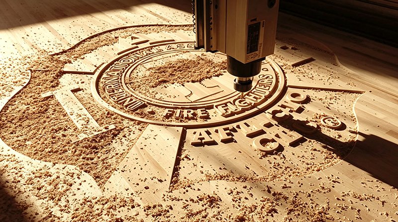
Material surrounding the characters is milled away, leaving the characters themselves raised. Pros: Superior durability, striking visual impact, and withstands frequent cleaning. Cons: Longest machining time and highest cost. Suitable for: Logo components, high-end products, and surfaces subject to frequent touching or cleaning.
High-precision CNC routing creates crisp raised embossed text on metal components. This marking method delivers durable, legible branding and part identification widely used within custom mechanical manufacturing and precision engineering assemblies.
Processing Method Selection Table
| Processing Method | Machining Speed | Tool Type | Typical | Relative Cost | Best Suited For |
|---|---|---|---|---|---|
| Method | Machining Speed | Tool Type | Typical Depth | Relative Cost | Best Suited For |
| Single-Line Text Milling | Fastest | V-bit / Ø0.2–0.8 mm end mill | 0.1–0.3 mm | Low | Serial numbers, small text |
| Profile Milling | Medium | Ø0.3–2.0 mm flat end mill | 0.2–0.5 mm | Medium | General nameplates, medium-sized text |
| Pocket Milling | Slow | Ø0.5–2.0 mm flat end mill | 0.3–1.0 mm | Medium to High | Colored logos, deep lettering |
| V-Carving | Medium | 60°/90° V-bit | 0.2–2.0 mm (variable) | Medium | Decorative lettering |
| Raised / Embossed Text | Slowest | Ø0.5–3.0 mm flat end mill | 0.5–2.0 mm | High | Premium logos and appearance-focused designs |
Ⅴ. Design Standards Quick Reference Chart
The hardness, toughness, and machinability of different materials directly affect the minimum machinable dimensions for CNC engraving. While soft materials are generally easy to process, issues such as burrs and deformation require attention; conversely, hard metals offer durability but place greater demands on cutting tools and machining parameters. Therefore, when designing text, factors such as character height, line width, character spacing, and engraving depth should be adjusted according to the material type. The following parameters serve as design references for various materials.
| Material Category | Representative Materials | Recommended Text Height | Recommended Stroke Width | Recommended Character Spacing | Recommended Engraving Depth |
|---|---|---|---|---|---|
| Plastics / Soft Metals | ABS, PC, POM, Nylon, aluminum sheets, etc. | ≥2 mm (3 mm or larger recommended) | ≥0.3 mm | ≥0.5 mm (0.6–0.8 mm recommended) | 0.2–0.5 mm |
| Common Metals | 6061 aluminum, 7075 aluminum, brass, copper, etc. | ≥2–3 mm | ≥0.4 mm | ≥0.6 mm | 0.2–0.5 mm |
| Hard-to-Machine Metals | Stainless steel, titanium alloys, etc. | ≥3 mm (4 mm or larger recommended) | ≥0.5 mm | ≥0.8 mm | 0.2–0.5 mm |
The parameters above represent typical ranges for CNC lettering designs; actual machining results are also influenced by factors such as tool diameter, character structure, machining method, and equipment rigidity. For small-scale text or complex typefaces, it is recommended to conduct sample tests prior to full-scale production to verify text clarity and machining stability.
Ⅵ. How Should You Choose a Font?
The results of CNC engraving depend not only on the choice of font and cutting tool but also closely on material properties. Differences in hardness, toughness, machinability, and thermal stability among materials directly affect machining difficulty, the clarity of the lettering, and surface quality. This overview covers common machining materials, those best suited for engraving, and key considerations for materials that are difficult to machine, helping you select the most appropriate processing strategy during the design phase.
Commonly used fonts
| Font | Type | Single-Line Font | Characteristics | Recommended Applications |
|---|---|---|---|---|
| ISO 3098 | Engineering drawing standard font | Some variants | Clear structure, sans-serif design, standardized proportions | Industrial part markings, engineering drawings |
| DIN 1451 | Industrial font | No | German standard font, uniform strokes, easy to machine | Nameplates, equipment panels |
| Simplex | Single-line font | Yes | Commonly used for CNC machining, simple toolpaths | Fast marking, serial numbers, part identification |
| Gothic / Gothic ISO | Sans-serif font | Some variants | Highly readable, simple geometry | General industrial text and labels |
| Arial | Sans-serif font | No | Widely compatible, easy CAD/CAM conversion | General product markings |
| Helvetica | Sans-serif font | No | Clean, modern appearance with balanced geometry | Premium product logos and appearance-focused designs |
Recommended Fonts
| Application | Recommended Fonts | Font Type | Description |
|---|---|---|---|
| Part Numbers / Serial Numbers | ISO 3098 / Simplex / DIN 1451 | Engineering standard fonts / Single-line fonts | Most stable and easy to machine; commonly used for high-volume production |
| Equipment Nameplates / Panel Markings | DIN 1451 / Arial / Helvetica | Industrial sans-serif fonts | High readability with consistent and standardized appearance |
| Logos / Brand Markings | Helvetica / DIN 1451 / Futura (simplified) | Sans-serif / Geometric fonts | Vector structures should be simplified for easier machining; suitable for appearance-focused parts |
| Molds / Fixtures Identification | ISO 3098 / Simplex / Gothic | Engineering fonts | Industry-standard styles with clear readability and long-term durability |
| Small Text Marking | Simplex / ISO single-line fonts / Simplified Arial | Single-line / Sans-serif fonts | Suitable for small text heights (≥2 mm) |
| Premium Appearance Parts | Helvetica / Futura / DIN 1451 | Design-oriented sans-serif fonts | Creates a clean, modern industrial aesthetic |
Ⅶ. What Are the Applications of Text Milling?
Model and Serial Number Identification:For Production Management and Quality Traceability
Product model numbers and serial numbers are the most common forms of permanent identification for industrial parts. Model numbers distinguish between different specifications, versions, or configurations, facilitating production, assembly, and inventory management while preventing the mix-up of parts. Serial numbers establish a unique identity for each product, supporting production records, inspection data, after-sales maintenance, and quality traceability. The absence of this information can easily lead to batch confusion and maintenance difficulties, and may even make it impossible to rapidly pinpoint quality issues.
Logos and Brand Names: For Product Identification and Branding
Logos and brand names serve primarily to enhance product recognition and brand image; they are commonly found on equipment housings, consumer products, industrial components, and high-end mechanical parts. Compared to labeling or printing, CNC milling and engraving offer superior durability, ensuring the markings remain clear over the long term. For high-value products, permanent branding not only prevents confusion but also elevates the product’s perceived quality and professional appearance.
Medical UDI and Aerospace Traceability Markings: Meeting Regulatory and Compliance Requirements
Markings on medical devices and aerospace components are not merely for displaying information; they are an essential element of quality management systems. Medical devices typically require UDI, batch, and manufacturing details to satisfy regulatory requirements and support full lifecycle traceability, while aerospace parts require the recording of information such as part numbers, manufacturer details, and batch data to ensure the traceability of every critical component. Failure to achieve clear, durable markings can lead to compliance risks and quality management issues.
Mold Identification and Production Management Markings: Enhancing Manufacturing Efficiency
Mold identification numbers serve primarily to distinguish between different molds, cavities, and production versions, facilitating daily management, maintenance, and the tracking of service life. In mass production, clear, permanent markings enable the rapid assessment of a mold’s status, thereby reducing production errors and improving maintenance efficiency. A lack of effective identification can easily lead to the mixing up of molds, the loss of maintenance records, and difficulties in quality analysis.
Ⅷ. How Should Cutting Tools be Selected?
In CNC engraving, the choice of tool type and size must align with the specific structure of the typeface. Different fonts vary in terms of stroke width, level of detail, and machining paths; using a tool that is too small can reduce efficiency, while one that is too large may fail to accurately reproduce the font’s details. Therefore, once a font is selected, the appropriate tool specifications should be determined by considering the text size, machining depth, and material properties. The following serves as a reference for matching common font types with recommended tools.
| Font Type | Recommended Tool Type | Common Tool Sizes | Application Notes |
|---|---|---|---|
| Single-Line Fonts | Ball end mills / Small-diameter end mills / V-bits | Ø0.2–0.8 mm | Suitable for small text and fast serial number marking |
| Engineering Standard Fonts | Small-diameter flat end mills / Small end mills | Ø0.3–1.0 mm | Stable for industrial standard markings and repeat production |
| Industrial Sans-Serif Fonts | Flat end mills / Small-diameter end mills | Ø0.5–2.0 mm | Suitable for common nameplates and panel text |
| Geometric Design Fonts | Small flat end mills / Ball end mills | Ø0.5–1.5 mm | Requires simplified geometry to avoid excessive details |
| Standard Sans-Serif Fonts | Flat end mills | Ø0.5–2.0 mm | Suitable for general product appearance markings |
| Large Text Fonts | Standard flat end mills | Ø1.0–3.0 mm | Suitable for logos, appearance markings, and deep engraving |
Ⅸ. Precautions for Processing Different Materials
The results of CNC engraving depend not only on the choice of font and cutting tool but also closely on material properties. Differences in hardness, toughness, machinability, and thermal stability among materials directly affect machining difficulty, the clarity of the lettering, and surface quality. This section outlines common machining materials, types suitable for engraving, and considerations for materials that are difficult to machine, helping you select the most appropriate processing strategy during the design phase.
What are the common materials?
| Material Category | Common Materials | Machining Characteristics |
|---|---|---|
| Aluminum Alloys | 6061, 7075 aluminum | The most widely used materials for text milling; easy to machine with excellent surface quality |
| Steel | Carbon steel, stainless steel | High strength but requires greater cutting forces and more robust tooling |
| Copper / Brass | Copper, H59 brass | Good electrical conductivity and stable machinability |
| Plastics | ABS, PC, POM (Delrin) | Easy to machine but requires proper cutting parameters to avoid burrs and melting |
| Engineering Plastics | PA (Nylon), PEEK | High-performance materials with excellent strength, but more prone to deformation |
| Wood | Hardwood, MDF | Easy to machine but may produce fiber burrs and rough edges |
Which materials are more suitable for processing?
| Material | Recommended Rating | Reason |
|---|---|---|
| Aluminum Alloys | ★★★★★ | Stable cutting performance, clean surface finish, and one of the best materials for text milling |
| Brass | ★★★★ | Smooth chip evacuation and excellent edge definition |
| ABS | ★★★★ | Easy to machine, but heat buildup needs to be controlled to prevent melting |
| POM (Delrin) | ★★★★★ | Low tendency to stick to cutting tools and excellent dimensional stability |
Which materials are difficult to machine, and what precautions are required?
| Material | Main Machining Challenges | Recommended Practices |
|---|---|---|
| Stainless Steel | Rapid tool wear caused by work hardening and high cutting resistance | Use appropriate cutting speeds, lower feed rates, and sufficient coolant/lubrication |
| Carbon Steel | High cutting forces and potential tool breakage | Avoid overly small tools and select proper cutting parameters to prevent edge chipping |
| Polycarbonate (PC) | Heat buildup can cause melting and poor edge quality | Reduce spindle speed, maintain high chip removal efficiency, and avoid excessive friction |
| Nylon (PA) | Burrs and dimensional deformation due to material flexibility | Use sharp tools and minimize excessive clamping pressure |
| Wood | Fiber tearing and rough surface edges | Follow the grain direction and use sharp cutting tools for cleaner results |
How can the formation of burrs be prevented?
When milling text, the key to avoiding burrs lies in the proper selection of cutting tools and the optimization of machining parameters. Sharp tools should be used to prevent the formation of burrs caused by dull tools crushing the material; additionally, spindle speed and feed rate must be appropriately matched to ensure stable cutting rather than a friction-based process. Climb milling is the preferred machining method to minimize tearing along the edges of the characters. Engraving depth is generally controlled between 0.2 mm and 0.6 mm, as excessive depth increases the risk of burrs. For plastic materials, temperature control is also necessary to prevent melting and stringing. If required, a slight chamfer or deburring step can be applied to achieve a cleaner finish on the lettering.
Ⅹ. How Does Text Milling Design Affect Machining Costs?
Factors Affecting Machining Difficulty
- Font Complexity
Font style is a primary factor influencing cost. Simple sans-serif fonts (such as ISO 3098 or DIN 1451) feature straightforward, continuous toolpaths and offer high machining efficiency. In contrast, complex fonts (such as script or decorative typefaces) involve numerous curves, intricate details, and frequent directional changes; these significantly increase toolpath calculation complexity and machining time, while also raising the risk of tool breakage and necessitating slower feed rates, thereby driving up costs.
- Engraving Depth
Greater engraving depth results in increased machining time and higher tool loads. Shallow engraving (0.2–0.3 mm) typically requires only a single pass, whereas deep engraving (over 0.6 mm) often necessitates multi-layer machining and places greater demands on chip evacuation and cooling. These factors not only extend the production cycle but also accelerate tool wear, leading to a significant rise in costs.
- Font Size
Smaller font sizes increase machining difficulty. Small text requires smaller-diameter tools (e.g., 0.2–0.5 mm); these tools lack rigidity, are prone to breakage, and require slower feed rates, all of which reduce overall machining efficiency. Conversely, larger fonts allow for the use of larger tools that cover a greater surface area per cut, resulting in lower unit costs.
- Materials
Material choice significantly impacts costs. Aluminum alloys and brass offer excellent machinability—allowing for high processing speeds and extended tool life—resulting in lower costs. Conversely, high-strength materials like stainless steel and titanium alloys require slower feed rates, cause greater tool wear, and demand longer processing times, leading to a substantial increase in costs. While plastics are easy to machine, they are prone to burr formation, which can raise post-processing costs.
- Curves and Structural Complexity
Text designs featuring numerous curves and frequent directional changes result in complex machining paths; the need for the tool to frequently decelerate and change direction reduces feed efficiency. Additionally, small-radius curves may require smaller cutting tools, further driving up costs. Consequently, linear designs are more cost-effective than those with complex curves.
- Engraving Location
The placement of the text also affects costs. Machining efficiency is highest when text is located on a flat surface that is easy to clamp. In contrast, text located in deep cavities, on sidewalls, or in areas requiring multiple part reorientations increases setup time and fixture complexity. Furthermore, working in confined spaces may necessitate longer tools or specialized toolpath strategies, thereby increasing both machining risks and costs.
XI. How Can the Design be Optimized?
Optimizing the design for CNC text milling essentially involves making the text “easier to machine,” thereby reducing machining time, minimizing tool wear, and improving yield rates. First, regarding font selection, prioritize standard sans-serif or single-stroke fonts—such as ISO 3098, DIN 1451, or Simplex—and avoid complex, decorative typefaces to reduce toolpath complexity. Second, regarding dimensions, avoid excessively small text; ensure that line widths and spacing accommodate the minimum tool accessibility requirements. Otherwise, the use of micro-tools becomes necessary, which significantly lowers efficiency and increases costs. Engraving depth should ideally be kept within a shallow range of 0.2–0.5 mm to avoid the tool wear and multi-pass machining associated with deep engraving.
Regarding structural design, minimize intricate curves and overly complex shapes; prioritize straight lines and large-radius fillets to ensure a more stable and smooth toolpath. Additionally, position the text on flat areas that are easy to clamp, avoiding deep cavities, sidewalls, or locations near edges, so as to minimize clamping complexities and machining difficulties. Furthermore, consider tool accessibility during the design phase: ensure the minimum line width exceeds the tool diameter (with a safety margin) to prevent issues such as the inability to engage the tool or the need for rework. Through these optimizations, machining becomes more efficient, stable, and cost-effective without compromising legibility.
XII. Common Design Errors & Solutions
In actual machining, the design of text and patterns affects not only the visual quality of the part but also directly influences tool selection, machining efficiency, and the final outcome. Many machining issues stem not from the equipment or process itself, but from a failure to fully consider manufacturing feasibility during the design phase. The following summary outlines common design errors, their potential impact on machining, and corresponding optimization solutions, serving as a reference for CNC engraving and signage design.
| Common Design Mistakes | Impact | Recommended Solutions |
|---|---|---|
| Using overly complex fonts (handwriting or decorative fonts) | Creates complicated toolpaths, increases machining time, and raises the risk of tool breakage | Use standard sans-serif or single-line fonts such as ISO 3098, DIN 1451, or Simplex |
| Text size is too small | Requires micro tools, reduces efficiency, and increases the risk of machining failure | Increase text height (≥3 mm recommended) and avoid text smaller than 2 mm |
| Stroke width is too thin | Tools may not fit properly, resulting in incomplete or inaccurate lettering | Maintain a minimum stroke width of 0.3–0.5 mm and match it with the tool diameter |
| Character spacing is too narrow | Causes letters to merge and reduces readability | Increase spacing to ≥0.5 mm (0.6–0.8 mm recommended) |
| Engraving depth is excessive | Requires multiple machining passes, increases tool wear, and may cause more burrs | Keep engraving depth within 0.2–0.5 mm for most applications |
| Using difficult-to-machine materials (e.g., stainless steel) | Increases machining difficulty, cost, and tool wear | Consider adding a nameplate or use carbide cutting tools designed for hard materials |
| Excessive curved geometry | Causes frequent tool direction changes and reduces machining efficiency | Simplify designs using straight lines or larger-radius curves |
| Text placed in difficult locations (deep cavities or side walls) | Makes fixturing difficult, requires longer tools, and increases vibration risk | Place text on flat, easily accessible surfaces whenever possible |
| Sharp internal corners | Cutting tools cannot create perfectly sharp corners | Add internal fillets with a radius ≥ the tool radius |
| Ignoring tool accessibility | Machining may fail or require rework | Verify tool paths, clearance, and accessibility before manufacturing |
| Engraving after surface finishing | Damages anodizing or coatings and exposes the base material | Engrave before surface finishing unless a filled-color engraving effect is required |
| Engraving in high-stress areas | Recessed text can act as a stress concentrator and potentially initiate cracks | Keep markings away from load-bearing areas, edges, and threaded holes (at least 5 mm clearance recommended) |
XIII. Conclusion
CNC engraving cuts material using a cutting tool; it is suitable for applications requiring deep machining (such as with metals), offers a strong three-dimensional effect, but is slower and may produce burrs. Laser engraving uses a high-energy laser to ablate the surface; it is fast and ideal for fine marking, though it offers limited depth and may result in discoloration (blackening) or heat-affected zones. The former focuses on structural machining, while the latter focuses on rapid marking.
FAQ
Q: What is the difference between CNC engraving and laser engraving?
CNC engraving cuts material using a cutting tool; it is suitable for applications requiring deep machining (such as with metals), offers a strong three-dimensional effect, but is slower and may produce burrs. Laser engraving uses a high-energy laser to ablate the surface; it is fast and ideal for fine marking, though it offers limited depth and may result in discoloration (blackening) or heat-affected zones. The former focuses on structural machining, while the latter focuses on rapid marking.
Q: Can logos be machined directly?
A: Logos can be machined via CNC, but they must first be converted into vector files and simplified for engineering purposes to ensure that line widths, spacing, and dimensions meet the tool’s machining requirements. Logos that are overly complex, contain excessive detail, or feature gradients require optimization; otherwise, stable machining may be impossible, or the results may be poor.
Q: Should surface treatment or text milling be performed first?
A: Generally, text milling should be performed before surface treatment, as CNC machining can damage surface coatings or oxide layers. Performing surface treatment before engraving increases the risk of surface damage or poor adhesion.
Q: What is the appropriate engraving depth?
A: For text milling, a depth of 0.2–0.5 mm is generally recommended; shallow engraving is suitable for markings and nameplates, offering clarity at a low cost. Depths exceeding 0.5 mm are used for high-contrast or durability requirements but increase machining time and tool wear; excessive depth can also lead to burrs.
Q: What are the best fonts for engraving?
A: The best fonts for CNC text milling are industrial sans-serif or single-line fonts such as ISO 3098, DIN 1451, and Simplex; their simple structures and uniform line widths facilitate the generation of stable toolpaths. Arial and Helvetica can also be used, provided details are simplified; complex, decorative fonts should be avoided.
Q: How much more expensive is text milling compared to screen printing or labeling?
A: Text milling is generally more expensive than screen printing or labeling. The cost for a single unit can be several to over ten times higher, primarily due to the requirements for programming, workholding, machining, and post-processing. While screen printing and labeling are suited for high-volume, low-cost production, milling is better suited for products requiring durability, a premium feel, and permanent marking.
Q: Is there an extra charge for small-batch prototyping?
A: Small-batch prototyping usually incurs additional costs. Since CNC machining involves fixed costs—such as initial programming, tooling preparation, and setup/calibration—the cost per unit is higher for smaller quantities. Costs can be reduced if the design is simple and dimensions are uniform; however, complex text or special materials may require additional fees for testing and process adjustments.
Q: How do I specify text milling on engineering drawings?
A: Drawings must clearly specify five details: the text content, font name, character height, depth tolerance, and machining method (optional). CAD files must be exported in DXF or SVG vector format, and text must be converted to paths to prevent errors caused by missing fonts on the supplier’s end. Please refer to Section 9, “How to Specify,” for details.
Q: What’s the typical lead time for text-milled parts?
A: Lead times depend on part complexity and quantity. For standard part machining combined with text milling, the lead time is 5–7 days for prototypes and 2–3 weeks for small batches. If a preliminary sample confirmation is required, add 2–3 days. Priority scheduling can be arranged for urgent orders.