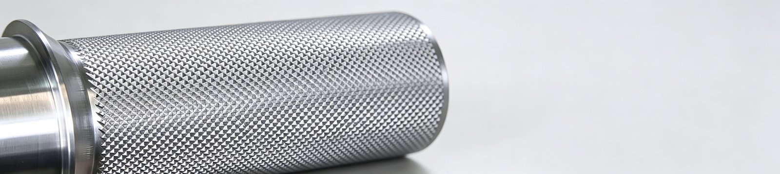
A knurled surface looks like a minor cosmetic detail. It changes how the part behaves in service — and not in the direction most engineers assume. The displaced metal that forms the pattern creates stress risers, not reinforcement. Choosing the wrong pattern, method, or pitch for a given material and diameter turns a functional grip feature into a rejected batch. This guide covers pattern selection, form vs cut knurling, pitch-by-diameter matching, DFM design rules, and the defects that show up when any of those variables is off.
Ⅰ. What Is Knurling?
Knurling is the process of forming a textured pattern on a cylindrical surface by displacing or cutting material with a hardened wheel or tool. The pattern serves four purposes: grip enhancement, torque transfer, press-fit retention, and diameter adjustment. A thumb screw uses knurling for grip. A valve stem uses it for torque. A metal insert in a plastic housing uses it for mechanical lock.
What knurling does not do is add strength. The ridges it creates are stress concentration features. Under fatigue or torsional loading, a knurled section can be weaker than a plain section of the same diameter. The pattern is a functional surface treatment, not a structural reinforcement.
Ⅱ. Knurling Patterns: Straight, Diagonal, and Diamond
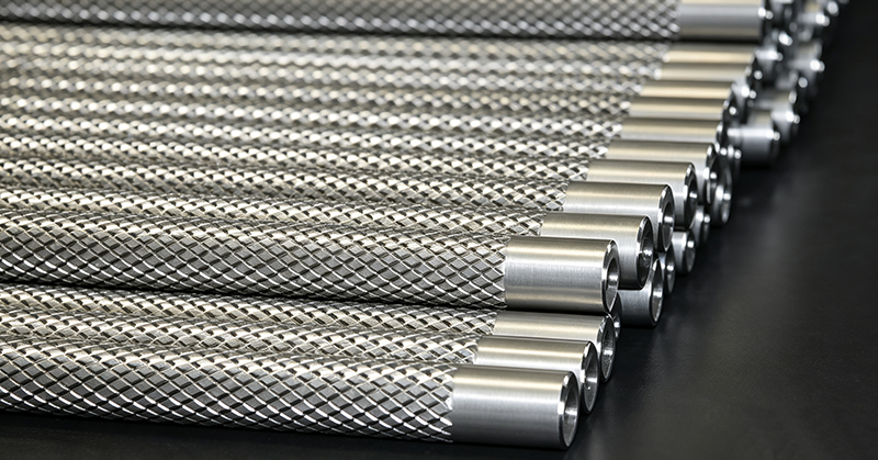
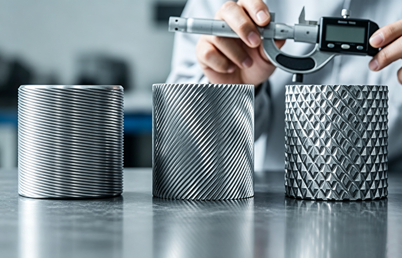
Three patterns cover the majority of production knurling:
- Straight (axial): lines run parallel to the part axis. Used for axial grip and press-fit retention.
- Diagonal (helical): lines run at an angle to the axis. Used for torque transfer where axial grip is secondary.
- Diamond: two diagonal sets cross to form a raised pyramidal pattern. The crossing angle is typically 30° (adjustable based on the knurling wheel specification). The most common pattern for knobs, thumb screws, and grip surfaces.
| Pattern | Best For | Limitation |
|---|---|---|
| Straight | Axial grip, press-fit inserts | Low torque resistance |
| Diagonal | Torque transfer, valve stems | Less grip than diamond |
| Diamond | General grip, knobs, thumb screws | Hardest to track correctly |
Secondary patterns — square, beveled, concave, convex — exist for specialized applications but are not standard production choices.
Ⅲ. Form Knurling vs Cut Knurling
The two methods produce visually similar patterns through fundamentally different mechanisms.
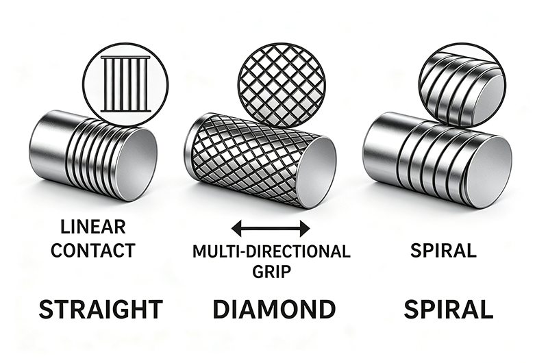
Form knurling pushes a hardened wheel into the rotating workpiece. Material flows plastically under pressure, creating ridges and valleys. The process slightly increases the outer diameter because material is displaced, not removed. Form tooling is cheaper and the process is faster, but it only works on ductile materials.
Cut knurling uses a cutting tool that removes material to form the pattern. The outer diameter stays constant. The method works on hard and brittle materials that cannot plastically deform. Tooling costs more, but the process is the only option for hardened steel, cast iron, and some plastics.
The decision follows material and tolerance:
| Decision Factor | Form | Cut |
|---|---|---|
| Material ductility | Required | Not required |
| OD tolerance | Changes OD by 0.3–0.5 mm | Holds OD |
| Tool cost | Lower | Higher |
| Surface finish | Smooth displaced ridges | Groove sidewall lay marks |
| Hardened steel | Will not work | Required |
| Gray cast iron | Will not work | Required |
A visual check tells you which method produced a finished part: cut knurling shows tool lay marks on the groove sidewalls; form knurling has smoother ridges where material flowed.
Ⅳ. Knurling Materials and Compatibility
Material hardness and ductility determine which method works. Form knurling requires ductility — the material must flow without cracking. Cut knurling removes material, so it works regardless of ductility, provided the tool is sharp and the material is not abrading the edge.
| Material | Form Knurling | Cut Knurling | Notes |
|---|---|---|---|
| Aluminum 6061 | Excellent | Good | Low pressure, clean pattern |
| Brass | Excellent | Good | Low tool wear, sharp ridges |
| Mild Steel 1018 | Good | Good | Standard choice, higher pressure than aluminum |
| Stainless 304 | Difficult | Good | Work-hardens; cut is more reliable |
| Stainless 316 | Difficult | Good | Galling risk; lubrication essential |
| Hardened Steel | Not viable | Required | Ductility too low for forming |
| Gray Cast Iron | Not viable | Required | Brittle; cannot plastic-deform |
| Titanium | Difficult | Good | Springback; needs sharp cut tool |
| Plastics (Delrin) | Moderate | Good | Form can crack brittle grades |
Stainless and titanium require cutting fluid during knurling. Without lubrication, the material galls on the tool, the pattern loses definition, and the tool edge degrades rapidly.
Ⅴ. Knurling Pitch: TPI and Selection
Pitch is the number of teeth per inch (TPI) on the knurling wheel. It determines how fine or coarse the pattern appears. Common pitches range from 12 TPI (very coarse) to 120 TPI (very fine).
The critical variable is the relationship between pitch and workpiece circumference. If the circumference is not evenly divisible by the pitch, the wheel does not land in the same groove on the second revolution. The result is double-tracking — two overlapping patterns that look blurred and feel rough.
This is the variable that most often causes a rejected knurling batch. The pitch table below matches TPI ranges to workpiece diameter:
| Workpiece Diameter | Recommended TPI | Pattern | Reason |
|---|---|---|---|
| < 3 mm (1/8″) | 64–96 | Straight / Diagonal | Fine pitch tracks better on small OD |
| 3–6 mm | 40–64 | Any | Standard small parts range |
| 6–12 mm (1/4–1/2″) | 25–40 | Diamond | Common knobs and thumb screws |
| 12–25 mm (1/2–1″) | 16–25 | Diamond | Standard grip applications |
| 25–50 mm (1–2″) | 12–16 | Diamond / Diagonal | Coarse grip, large handles |
| > 50 mm (2″) | 8–12 | Diagonal | Coarse; avoids pattern overlap |
The rule: circumference ÷ pitch must be a whole number. For a 10 mm diameter part, circumference is 31.4 mm. At 33 TPI (pitch = 25.4 ÷ 33 = 0.77 mm), the tooth count is 31.4 ÷ 0.77 = 40.8 — not a whole number, so the pattern will double-track. To fix it, adjust the pre-knurl OD to 9.8 mm: circumference becomes 30.8 mm, and 30.8 ÷ 0.77 = 40 — a whole number, and the pattern tracks cleanly. At 25 TPI (pitch = 25.4 ÷ 25 = 1.016 mm), 31.4 ÷ 1.016 = 30.9 — again not a whole number, and the pattern will double-track.
Ⅵ. DFM Design Rules for Knurling
Most knurling failures are designed in before the part reaches the lathe. The rules below cover the dimensions that matter.
| Rule | Value | Reason |
|---|---|---|
| Minimum shaft diameter | ≥ 6 mm | Smaller diameters bend under knurling pressure |
| Shoulder / edge clearance | ≥ 1 mm | Prevents tool crash into adjacent features |
| Wall thickness (hollow parts) | ≥ 2× pitch depth | Prevents ovaling or bending |
| Pre-knurl OD (form) | Reduce by 0.3–0.5 mm | Forming displaces material outward |
| Pre-knurl OD (cut) | Final OD | Cutting removes material; OD unchanged |
| Lead-in chamfer | 30–45° × 0.5 mm | Helps tool engage without chipping |
| Knurling length | ≤ 3× diameter | Longer runs risk pattern drift |
| Post-knurl tolerance | ±0.1 mm typical | Knurling is not a precision operation |
Surface finish interacts with the knurling pattern after production:
- Anodizing fills valleys and reduces pattern depth. If the part will be anodized, specify a deeper initial pattern.
- Bead blast dulls peaks. Acceptable for grip; not acceptable for precision press-fit.
- Plating adds 5–15 µm of thickness. Account for this in press-fit calculations.
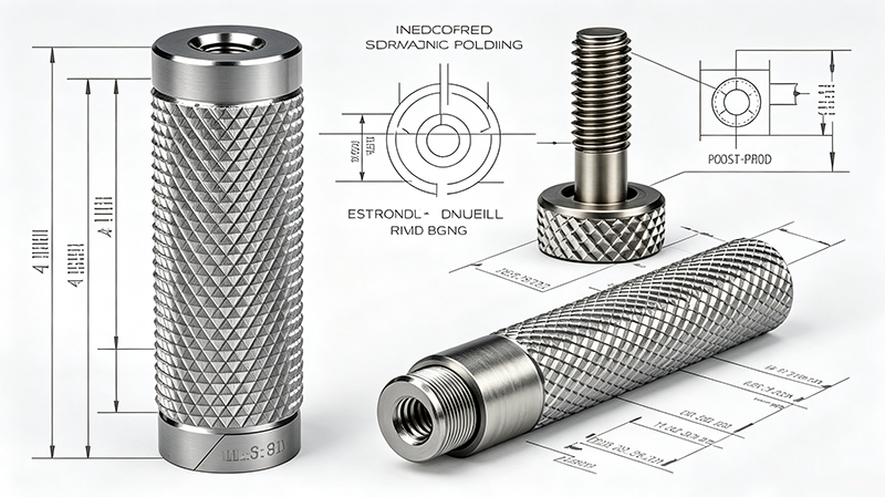
On the drawing, specify three things explicitly: pattern (straight / diagonal / diamond), pitch (TPI), and method (form / cut). Leaving the method open defaults the supplier to form knurling, which may not work for the specified material.
Ⅶ. Common Knurling Defects and Troubleshooting
When a knurling batch comes back wrong, the cause is usually one of seven issues. The table maps each defect to its root cause and fix.
| Defect | Likely Cause | Fix |
|---|---|---|
| Double tracking | Circumference not divisible by pitch | Change TPI or adjust OD by 0.05–0.1 mm |
| Blurred pattern | Insufficient pressure (form) or worn tool (cut) | Increase feed pressure or replace knurl wheel |
| Bent or oval part | Wall too thin for knurling pressure | Increase wall thickness or switch to cut knurling |
| Pattern does not form | Material too hard for form knurling | Switch to cut knurling |
| Surface galling | Stainless or titanium run dry | Apply cutting fluid; use sharp cut tool |
| Chipped knurl wheel | Tool engaged too abruptly | Add lead-in chamfer; reduce entry feed rate |
| Inconsistent depth | Worn spindle bearings or loose tool holder | Check machine rigidity; tighten tool holder |
Double-tracking is the most common and the most expensive — the part often looks superficially acceptable but fails grip or press-fit function. The fix is always in the pitch-to-diameter ratio, not in the tool or the machine.
[IMAGE: Common knurling defects — double track, blurred pattern, bent thin-wall part]
Ⅷ. Knurling Applications
Knurling applications group by function, not by industry.
Grip: tool handles, thumb screws, instrument knobs, control dials. The pattern improves friction between the user’s hand and the part.
Torque transfer: valve stems, adjustment screws, fastener heads. The pattern lets the user apply torque without slipping.
Press-fit retention: metal inserts in plastic housings. The knurl provides a mechanical lock that prevents the insert from rotating or pulling out under load. This is often a lower-cost alternative to a high-tolerance press-fit.
Aesthetics: decorative end caps, consumer product trim. The pattern is visual, not functional.
Repair: retexturing a worn cylindrical surface. Historically used to extend the life of cylinders and shafts where replacement was not practical.
The one application knurling does not serve is structural reinforcement. If a part needs more strength, add material or change the geometry. A knurl adds stress concentration, not load capacity.
Ⅸ. Conclusion
Knurling is a functional surface treatment, not a structural feature. Pattern selection follows function — straight for axial grip, diagonal for torque, diamond for general use. Form versus cut follows material ductility. Pitch follows workpiece diameter, and the circumference-to-pitch ratio is the variable that determines whether the pattern tracks cleanly or double-tracks. DFM rules on shaft diameter, wall thickness, and lead-in chamfer prevent most production failures.
If your part needs a knurled feature, upload the CAD file for a DFM review. Keywin’s CNC engineers verify the knurling pattern, pitch, and material match before the first cut, so the pattern comes out right the first time.
FAQ
1. Does knurling add strength to a part?
No. Knurling creates stress concentration features. The displaced or cut material forms ridges that act as stress risers under fatigue and torsional loading. Use knurling for grip, torque, or press-fit retention — not for structural reinforcement.
2. When should I choose cut knurling over form knurling?
Choose cut knurling for hardened steel, gray cast iron, brittle plastics, or any case where the OD tolerance must be held tight after knurling. Form knurling changes the OD by 0.3–0.5 mm; cut knurling does not.
3. How do I prevent double-tracking on a diamond knurl?
Match the workpiece circumference to the pitch. Circumference ÷ pitch must equal a whole number so the knurling wheel lands in the same groove on each revolution. Adjust the TPI or the pre-knurl OD by 0.05–0.1 mm to hit that ratio.
4. Can I knurl a thin-walled tube?
Only if the wall thickness is at least 2× the pitch depth. Below that, the knurling pressure ovalizes or bends the tube. For thin walls, switch to cut knurling or increase the wall thickness in the design.
5. What TPI should I use for a 10 mm diameter knob?
The standard range for 6–12 mm diameters is 25–40 TPI. For a 10 mm knob, 33 TPI is a common production choice — adjust the pre-knurl OD to 9.8 mm so the tooth count lands on a whole number (40 teeth) and the pattern tracks cleanly.
6. Should I specify form or cut knurling on my drawing?
Specify both the method (form / cut) and the pitch (TPI). If you leave the method open, the supplier defaults to form knurling, which may not work for your material. A drawing that says only “diamond knurl” leaves the supplier guessing.