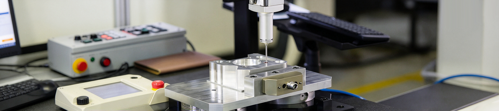
CNC machining, tighter tolerances generally make parts more challenging to manufacture. For example, a tolerance of ±0.01 mm requires a dimension to remain within a very narrow range. Even if a CNC machine can produce one part that meets this requirement, it does not necessarily mean the same level of accuracy can be consistently maintained throughout an entire production batch.
This is because machining accuracy depends not only on machine capabilities but also on factors such as material properties, part geometry, workholding methods, tool wear, temperature variations, and measurement techniques. Achieving consistent tight tolerances requires careful control of part design, machining processes, and quality inspection.
This article covers key design considerations, common manufacturing risks, process control methods, and inspection requirements for tight tolerance machining. It aims to help design engineers and procurement professionals maintain critical part functionality while managing machining complexity, lead times, and manufacturing costs.
Ⅰ. When Does a Part Need a Tight Tolerance
Start with the function of the feature
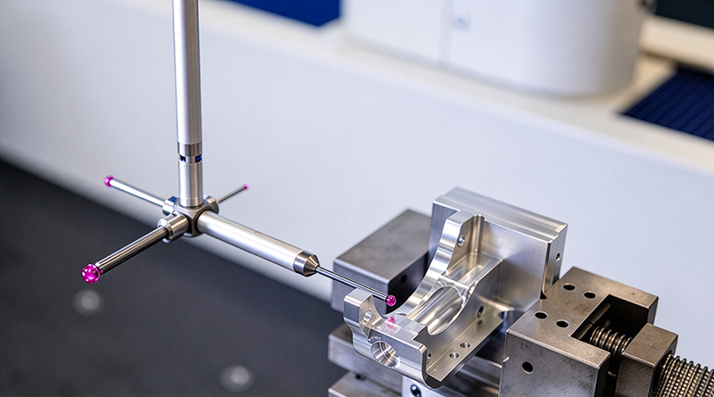
Different features require different levels of control. Bearing seats, mating holes, sealing faces, locating holes, and rotating shafts often need tighter dimensional or geometric tolerances so that the part assembles and operates correctly.
For example, variation in a bearing seat can affect fit stability. A sealing face can meet its size requirement and still leak because its flatness is inadequate. Tolerances should therefore follow the part’s function rather than applying the same strict limit to every dimension.
Apply tight tolerances only to critical features
Not every dimension needs a tight tolerance. Overly strict requirements on features that do not affect assembly, fit, or performance usually add machining time, inspection work, and cost.
Designers can use the following principles:
- Non-critical dimensions: Apply an appropriate general tolerance and identify the governing standard and class on the drawing.
- Critical fit dimensions: Specify individual limits for features that affect assembly accuracy, sealing, or operating clearance.
- Assembly relationships: Analyse the tolerance stack before assigning component tolerances so that accumulated variation does not prevent assembly.
- Manufacturing feasibility: Review requirements that may be difficult to produce or inspect through DFM before production. The designer must approve any tolerance change.
This approach directs manufacturing and inspection effort toward the features that protect part performance.

Ⅱ. Use functional datums and GD&T
Datums establish the reference used to manufacture and inspect the part. The datum system should reflect how the part locates in the final assembly. Otherwise, individual dimensions may pass while the assembled part remains misaligned.
Dimensional and geometric tolerances control different conditions. A bore can meet its diameter requirement without having the correct position, orientation, or form. If the bore must align with another component, the drawing may also need a GD&T control such as position or perpendicularity.
Common geometric controls include:
- Position controls the location of a hole, shaft, or other feature relative to specified datums.
- Flatness controls the form of a surface and is often relevant to sealing or precision contact faces.
- Parallelism and perpendicularity control orientation between features or relative to a datum.
- Profile controls variation of a complex surface from its true geometry.
- Runout controls variation of a rotating surface relative to a datum axis.
Appropriate GD&T communicates functional requirements more clearly than using smaller size tolerances to control geometric relationships.
Ⅲ. Which Design Features Increase Manufacturing Risk
Part geometry can make the same nominal tolerance much harder to maintain. Buyers do not need to design the supplier’s process, but they should recognize features that require early review.
| Design condition | Why it creates risk | What the buyer should define or discuss |
|---|---|---|
| Thin walls | Clamping and cutting forces can distort the part | Free-state acceptance, wall thickness, permitted distortion, and inspection setup |
| Long or slender features | Deflection can create taper, bending, or chatter | Functional length, support restrictions, straightness, and inspection locations |
| Deep small-diameter holes | Tool access, chip evacuation, and inspection are difficult | Depth-to-diameter requirement, bottom condition, surface finish, and measurement method |
| Tight relationships across several faces | Multiple setups can introduce datum-transfer error | Functional datum structure and the relationships that are truly critical |
| Heavy material removal | Residual stress can move the part after roughing | Material condition, stabilization needs, and final free-state requirement |
| Tight dimensions before and after treatment | Heat treatment or coating can change size | Acceptance state, masking, process allowance, and post-treatment inspection |
| Difficult-to-access features | A feature may be machinable but difficult to verify | Inspection access, probe or gauge method, and any permission for destructive testing |
Early DFM review is especially important when several of these conditions appear on the same part. The purpose is not to obtain every internal process detail. It is to confirm that the proposed route addresses the actual risks and that the finished feature can be inspected reliably.
Ⅳ. How Should Tight Tolerances Be Specified
A supplier can quote and manufacture only against the information provided. Ambiguous requirements create assumptions, repeated clarification, or additional risk in the quotation.
Use a functional datum system
Datums should reflect how the part locates in assembly. A mounting face, locating hole, or functional axis is often more useful than a convenient non-functional surface. If manufacturing and inspection use different interpretations of the datum, both parties can obtain internally consistent results that do not agree.
Separate general and critical tolerances
State the applicable general-tolerance standard and class, then identify critical features individually. This shows which dimensions follow the drawing default and which need special manufacturing and inspection control.
Do not use an unusually tight title-block tolerance to solve a local functional problem. It can apply expensive controls to many non-critical dimensions.
Define the material and condition completely
Material grade alone may not be enough. Heat-treatment condition, hardness, product form, prior processing, and residual stress can affect dimensional stability and machinability. If material substitution is permitted, identify who may approve it and which properties must remain equivalent.
State the final acceptance condition
The drawing and purchase order should state whether dimensions apply before or after heat treatment, anodizing, plating, polishing, or another finishing process. Critical holes, threads, bearing fits, and sealing faces may require masking, process allowance, or machining after treatment. These requirements should be settled before quotation.
Ⅴ. How Should the Manufacturing Process Be Controlled
Buyers do not normally need the supplier’s complete process documentation. They should, however, confirm that the process can maintain the requirement throughout the batch rather than produce only one acceptable sample.
Drawing and DFM review
Before production, the supplier should review the tightest dimensions, critical features, datum relationships, material condition, heat treatment, surface finishing, quantity, inspection methods, and reporting requirements. A non-critical tolerance that adds operations without a functional reason should be raised during DFM review rather than changed without approval.
Process and workholding planning
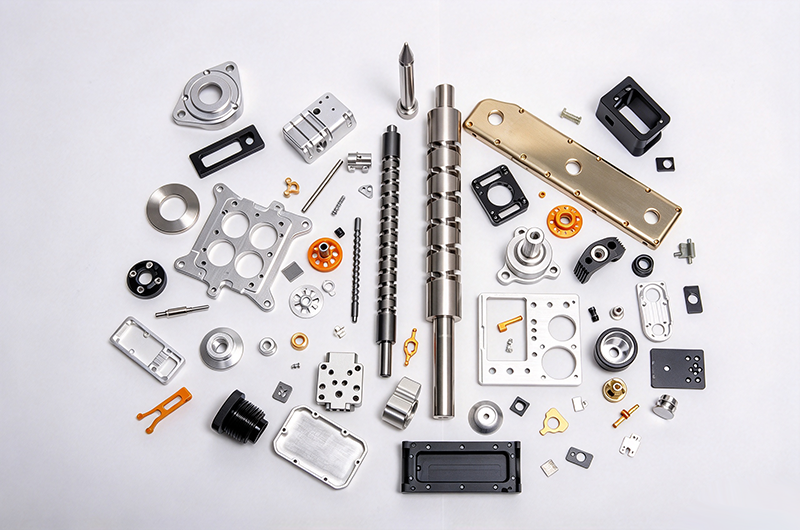
Depending on the part, the route may separate roughing from finishing, leave controlled stock for a final operation, machine related features in one setup, use dedicated workholding, or apply reaming, boring, grinding, honing, or wire EDM. No single process automatically guarantees a tolerance. The route must match the material, geometry, feature, and quantity.
First-article and in-process inspection
First-article inspection confirms the program, setup, datum interpretation, and measurement method before the production run continues. In-process inspection identifies trends caused by tool wear, temperature, or setup change. Final inspection confirms that the delivered parts meet the drawing and order.
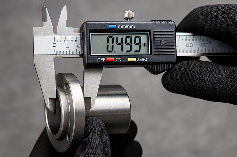
Inspection frequency should reflect tolerance risk, process stability, quantity, and customer requirements. Complete inspection is appropriate when the contract or risk requires it, but it should not be assumed for every close-tolerance feature.
Ⅵ. How Should Close Tolerance Parts Be Inspected
A tolerance can be controlled only when the measurement process can verify it with suitable uncertainty. Display resolution is not the same as measurement accuracy. Instrument performance, calibration, fixturing, operator method, measuring force, surface condition, and temperature can all affect the result.
| Inspection method | Typical use | Important consideration |
|---|---|---|
| Micrometer | Accessible external sizes, thicknesses, and diameters | Does not establish axis location or complex geometry |
| Bore gauge, air gauge, or dedicated gauge | Repetitive holes and internal fit features | Requires a defined setting method and suitable masters |
| Coordinate measuring machine CMM | Position, profile, and relationships among features | Probe access, fixturing, datum alignment, and evaluation strategy affect the result |
| Vision measurement | Small or optically accessible features | Edge definition and surface condition can affect the reading |
| Surface roughness tester | Specified Ra or other texture parameters | Measurement direction, location, and applicable parameters should be agreed |
| Functional gauge | Repeatable pass or fail verification of a defined fit | Useful for acceptance but may not provide variable measurement data |
Temperature can materially affect dimensional results. For illustration, a 300 mm aluminium feature measured 5 °C above the reference temperature could be about 0.035 mm longer if a coefficient near 23 µm/m·°C is assumed. The actual change depends on the alloy, temperature distribution, and measurement conditions, but the example shows why a warm part and a stabilized part may produce different results.
If the project requires an inspection report, agree during quotation on the measured features, method, acceptance state, sampling level, and report format. This prevents the parts from being completed before anyone discovers that the available record does not support approval.
Ⅶ. How Do Heat Treatment and Surface Finishing Affect Tolerances
A feature that is in tolerance after machining may not remain in tolerance at the end of the production route.
Heat treatment can change dimensions through thermal distortion, redistribution of residual stress, and metallurgical transformation. Thin, asymmetric, or heavily machined sections are often more sensitive. Critical features may need process allowance, stabilization, and a defined finishing operation after treatment.
Surface finishing also changes the acceptance condition:
- Anodizing changes aluminium surfaces, but the inward and outward portions of coating growth depend on the alloy and process. Critical holes, threads, and fits may need process-specific allowance or masking.
- Plating adds material to exposed surfaces. With a uniform deposit, a bore diameter may decrease by approximately twice the coating thickness, subject to actual process distribution.
- Blasting, polishing, and deburring remove or reshape material and can affect edge breaks, small features, surface texture, and dimensions measured near an edge.
Features that must remain uncoated should be identified clearly. Any final dimension affected by post-processing should be reinspected in its specified acceptance state.
Ⅷ. How Do Tight Tolerances Affect Cost and Lead Time
There is no universal cost multiplier. The added cost comes from the controls needed to maintain and verify the requirement.
Typical cost drivers include additional engineering review, more rigid or dedicated workholding, separate roughing and finishing operations, slower finishing passes, additional setups, tool monitoring, first-article and in-process inspection, CMM programming, reporting, treatment allowance, and higher scrap risk.
The tightest one or two features often determine the process class for the entire part. Adding another critical feature to a route already designed for precision may have a limited effect. Introducing the first close-tolerance feature can change the workholding, finishing method, inspection plan, and reporting requirement.
Designers can control cost by limiting tight tolerances to functional features, separating general and special tolerances clearly, using functional datums, completing tolerance-stack analysis, requesting only the inspection records needed, and defining post-treatment acceptance before drawing release.
Ⅸ. What Should a Close Tolerance Machining RFQ Include
A complete RFQ supports a faster and more reliable feasibility review. Include:
- 3D CAD model
- Fully dimensioned 2D drawing with revision level
- Applicable general-tolerance standard and class
- Individually identified critical tolerances
- GD&T callouts and datum system
- Material grade and condition
- Heat-treatment requirements
- Surface texture, coating, or plating requirements
- Whether dimensions apply before or after finishing
- Quantity and repeat-order expectations
- Functional note for especially critical features
- Required inspection method, sampling level, and records
- Any first-article, CMM, or full dimensional-report requirements
A 3D model communicates nominal geometry. It does not replace a controlled 2D drawing that defines tolerances, datums, finishing, and acceptance requirements.
Ⅹ. Conclusion
Close tolerance machining depends on alignment among design requirements, datum strategy, process planning, thermal and tool control, post-processing, and inspection. Machine accuracy is only one part of that system.
For an effective feasibility review, provide the 3D model, toleranced 2D drawing, material condition, quantity, finishing requirements, and required inspection records. If you are evaluating a precision-machined part, Keywin can review these inputs against its CNC machining process before the production route is confirmed.
Frequently Asked Questions
1. What is considered close tolerance machining?
There is no single threshold for every part. It generally means requirements tighter than normal shop practice, supported by a manufacturing and measurement plan capable of maintaining them repeatedly.
2. How tight can CNC machining hold?
It depends on the material, feature size, geometry, workholding, process route, quantity, final condition, and inspection method. A specific capability should be confirmed only after these conditions are reviewed.
3. Does every tight tolerance feature need CMM inspection?
No. The inspection method should match the feature and acceptance requirement. A micrometer or gauge may suit an accessible diameter, while a CMM is often appropriate for position, profile, and relationships among several features.
4. Should tolerances apply before or after surface finishing?
The drawing and purchase order should state the required acceptance condition. This is especially important for holes, threads, fits, sealing faces, and features affected by heat treatment, anodizing, or plating.
5. Do close tolerance parts always need complete inspection?
No. Inspection frequency should reflect risk, process stability, quantity, and customer requirements. A stable process may use first-article and interval inspection, while some critical applications require every part to be inspected.
6. Which inspection records should be requested?
Request only the records needed to support the part’s function and approval process. Define the measured features, method, sampling level, acceptance state, and report format before production.