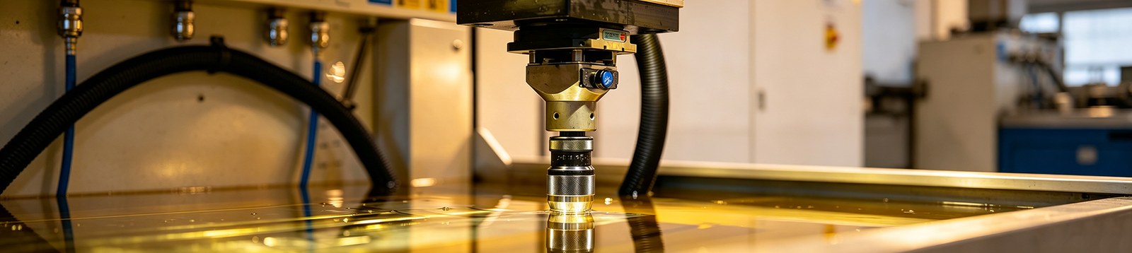
What Is Sinker EDM?
Choose sinker EDM when a part needs a blind cavity, a deep internal rib, or a shaped detail that a rotating cutter cannot reach reliably. The process uses a shaped electrode and controlled electrical discharges to reproduce that electrode form in an electrically conductive workpiece. Wire EDM is usually the cleaner choice for a through-profile with a viable wire path, while CNC milling is normally the lower-cost route for accessible bulk removal and ordinary pockets. Selecting the wrong process can add avoidable electrode work, setup time, surface treatment, and inspection risk.

Sinker EDM is also called die-sinking EDM, die sinker EDM, ram EDM, cavity EDM, plunge EDM, or sink EDM. These names describe the same family of shaped-electrode EDM operations. This article uses sinker EDM as the primary term.
Select the Process by Geometry and Access
Start by considering part geometry and whether the machining area is accessible. The table below compares the typical applications of Sinker EDM, Wire EDM, and CNC milling.
| Decision factor | Sinker EDM | Wire EDM | CNC milling |
|---|---|---|---|
| Best geometry | Blind or three-dimensional internal cavities | Through-cut profiles and contours | Features a cutter can reach |
| Tooling | Shaped, purpose-made electrode | Continuously fed wire | Standard or special cutting tools |
| Access requirement | Electrode needs a usable approach into the cavity | Wire needs a start hole or edge entry plus a through path | Tool needs line-of-sight and clearance |
| Workpiece requirement | Electrically conductive | Electrically conductive | Depends on cutter and material |
| Main cost driver | Electrode design, manufacture, wear, and burn count | Cut length, thickness, threading, and skim passes | Tooling, setups, toolpath time, and material removal volume |
| Typical role | Finish inaccessible cavities or hardened details | Cut detailed profiles after a through path is available | Remove accessible stock and general features |
Use this table as a first filter, not a capability promise. A part can use more than one process: milling can remove most of the stock, sinker EDM can finish a blind detail, and wire EDM can cut a separate profile. The economical route depends on geometry, material condition, tolerance, surface requirement, quantity, and inspection plan.
How Sinker EDM Creates a Cavity
Sinker EDM removes material through repeated electrical discharges across a controlled gap between the electrode and the workpiece. The electrode does not mechanically cut the workpiece, but it is not a simple stamp either: its geometry, discharge gap, wear behavior, orbiting strategy, and finishing sequence all affect the final cavity.
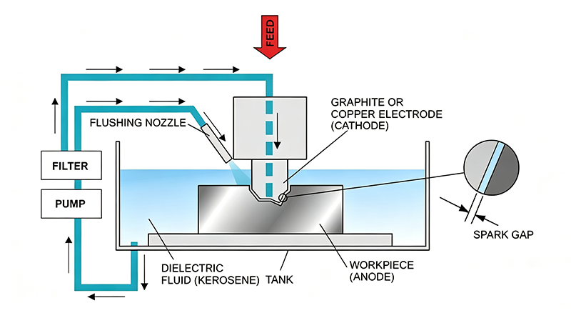
The workpiece must be electrically conductive. The dielectric fluid separates the electrode and workpiece until controlled breakdown occurs, then also helps cool the gap and carry debris away. Hardness does not replace the conductivity requirement; hardened steels and many conductive hard materials are suitable, while ordinary insulating plastics and ceramics are not.
A typical job follows this sequence:
1. Review the drawing for cavity geometry, electrode access, datums, material condition, tolerance, and finish.
2. Design the electrode with allowance for the discharge gap and planned wear compensation.
3. Machine and inspect the electrode before it reaches the EDM machine.
4. Fixture and align the workpiece to the required datum system.
5. Control the pulsed discharge, servo feed, dielectric delivery, and flushing.
6. Perform roughing and finishing burns, then clean and inspect the cavity.
The key control problem is stability. Poor debris evacuation can lead to unstable arcing, pitting, taper, slow removal, or inconsistent finish. Deep, narrow cavities are therefore not simply a question of electrode reach; they also need a viable flushing path and a process plan that accounts for wear.
The Electrode Is Part of the Part Design
In sinker EDM, the electrode is a designed production tool. It is normally an inverse of the required cavity, adjusted for the working gap and for the planned roughing or finishing burn. That is why a change to a small internal radius, deep rib, texture requirement, or tolerance can change electrode count and quote cost.
Graphite and copper are common electrode materials. Graphite can be a practical choice for larger or higher-energy burns; copper is often used where fine electrode detail or a finishing strategy suits it. Copper-tungsten may be evaluated for demanding wear or detail requirements, including certain conductive hard-material applications, but it adds material and electrode-machining cost.
| Electrode choice | Typical reason to consider it | Design or production caution |
|---|---|---|
| Graphite | Efficient electrode machining and robust roughing options | Fine unsupported details can be fragile; dust handling matters |
| Copper | Fine detail and finishing-oriented electrode work | Slower electrode machining and heavier handling can affect cost |
| Copper-tungsten | Wear-sensitive or small-detail applications | High material and machining cost needs a feature-specific case |
Electrodes wear even though the process is non-contact. End wear shortens the electrode, corner wear can round fine edges, and uneven wear can leave taper or geometry drift in a deep burn. Separate roughing and finishing electrodes can make the final cavity more predictable, but they also increase electrode preparation and setup.
When Sinker EDM Fits the Part
Sinker EDM is strongest when the feature, rather than the material name alone, creates the problem. Blind cavities, closed-bottom pockets, deep narrow ribs, shaped recesses, small internal radii, and details machined after hardening are common candidates. The process can also help when a thin feature cannot tolerate the side force of conventional cutting.
It is not a universal substitute for milling. If an end mill can reach the feature with a practical radius, stable toolpath, acceptable tool life, and required finish, milling usually removes material more quickly and with less electrode preparation. The same logic applies to a through-cut: if a wire has an entry and exit path, wire EDM services may offer the simpler EDM route.
| Feature | Why conventional milling may struggle | Why sinker EDM may fit | What to confirm on the drawing |
|---|---|---|---|
| Blind cavity | Cutter reach, corner radius, or hardened stock limits the route | Shaped electrode burns a closed-bottom form | Depth, access, radius, datum, flushing room |
| Deep narrow rib | Small cutter deflection and tool breakage risk | Thin electrode reaches without lateral cutting force | Rib width, depth, electrode stiffness, relief |
| Internal form after hardening | Tool wear and access may become limiting | Thermal removal is not based on conventional cutter contact | Heat-treatment sequence and surface requirement |
| Small internal radius | End-mill radius sets a physical floor | Electrode geometry can reduce the attainable radius | Radius is still not mathematically zero |
| Delicate wall or feature | Cutting force can distort or damage the part | Non-contact discharge reduces mechanical cutting force | Thermal effects, remaining stock, inspection method |
Plan Surface Quality and Accuracy Together
Sinker EDM can produce detailed cavities, but a generic claim of “high precision” is not enough for a drawing. Final size and finish depend on electrode accuracy, gap compensation, material, cavity depth, flushing, discharge settings, burn sequence, setup stability, and how the feature is inspected.
Overcut is the difference created by the working gap and compensation strategy. If compensation or wear control is wrong, the cavity can be oversize, undersize, tapered, or inconsistent from one depth to another. Tight requirements also need a clear datum-transfer plan; an accurate electrode cannot correct a workpiece that was set up against the wrong reference.
EDM is a thermal process. The burned surface may contain a recast layer and a heat-affected region; their condition depends on material and settings. Where fatigue performance, polishing, coating adhesion, sealing, or a defined surface texture matters, identify that requirement in the drawing and agree on any finishing, removal, or inspection step before production.
Do not request “perfectly sharp” internal corners. Corner geometry is limited by electrode form, working gap, wear, and process stability. When mold texture or a defined EDM finish is functional, state it with an agreed finish designation such as VDI surface finish rather than an informal visual note.
Design the EDM Feature Before Quotation
A clear drawing reduces rework because it lets the supplier choose the electrode strategy before the job is priced. Mark each blind and through feature, then tie critical dimensions to an unambiguous datum system. Separate functional tolerances and surface requirements from cosmetic preferences so the process is not forced into unnecessary finishing burns.
Use these checks during DFM review:
- Allow an achievable internal radius instead of specifying a theoretical zero radius.
- Avoid deep, narrow cavities that leave no room for stable flushing.
- State material grade, heat-treatment condition, and whether the feature is machined before or after hardening.
- Identify where recast removal, polishing, grinding, coating, or texture is required.
- Leave stock where another finishing process follows EDM.
- Flag complex cavities early so electrode access, split electrodes, and inspection can be planned.
These details also explain why sinker EDM cost is not a machine-hour question alone. Electrode count and complexity, cavity volume and depth, material condition, finish, tolerance, workholding, burn strategy, inspection, and post-EDM operations all change the production route. Relaxing a nonfunctional cosmetic finish or an unrealistic internal-radius requirement can sometimes remove an electrode or finishing operation.
What to Include in a Sinker EDM RFQ
Provide a 3D CAD model and controlled 2D drawing, plus the material grade, condition, heat treatment, quantity, and delivery need. Identify blind versus through features, critical dimensions, datums, internal radii, cavity depths, surface finish, surface-integrity needs, and any existing electrodes.
For a manufacturability review, Keywin can assess whether CNC machining services, wire EDM, sinker EDM, or a combined route fits the stated geometry and material condition. Include the drawing, the features that drive the process choice, tolerance, finish, quantity, and inspection requirements so the review is based on the part rather than a generic capability claim.
Frequently Asked Questions
1. What is another name for sinker EDM?
Die-sinking EDM, die sinker EDM, ram EDM, cavity EDM, plunge EDM, and sink EDM are commonly used names for the same shaped-electrode EDM process. The wording varies by region and application, but the defining feature is a formed electrode that creates a cavity or internal geometry in a conductive workpiece.
2. How does sinker EDM differ from wire EDM?
Sinker EDM uses a shaped solid electrode for blind or three-dimensional cavities. Wire EDM uses a continuously fed wire to cut a profile through the workpiece. The first selection question is access: a viable wire path points toward wire EDM; a closed-bottom cavity or internal form points toward sinker EDM.
3. Can sinker EDM machine nonconductive materials?
No. The workpiece needs sufficient electrical conductivity for controlled discharges to remove material. Hardness is a separate issue: a conductive hardened steel can be a good EDM candidate, while an ordinary insulating plastic cannot be machined by this process.
4. Does the electrode touch the workpiece?
No. A dielectric-filled working gap separates electrode and workpiece, and the machine controls that gap during the burn. The lack of mechanical contact reduces cutting force, but the electrode still erodes and needs wear control.
5. Can sinker EDM make perfectly sharp internal corners?
No. The achievable corner is affected by electrode geometry, discharge gap, wear, flushing, and the planned finish. Sinker EDM can create internal radii that are difficult for a conventional end mill, but the drawing still needs a practical radius requirement.
6. When is sinker EDM better than CNC milling?
Use sinker EDM when the final feature is inaccessible to a cutter, is a blind or shaped internal cavity, needs a smaller practical internal radius, or must be created after hardening. Use milling for accessible stock removal and ordinary pockets. Many tooling parts use both processes in sequence.