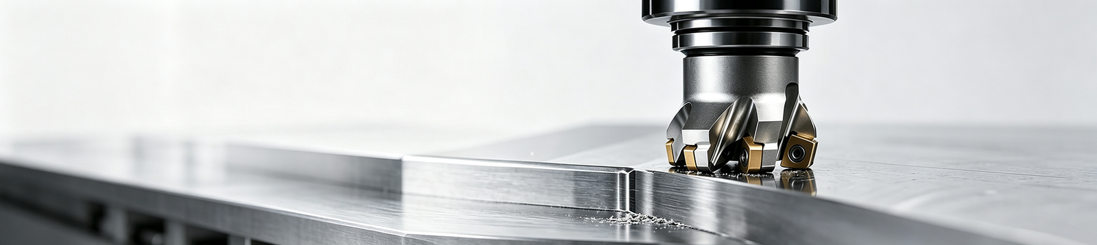
Peripheral milling removes material with the cutting edges on the circumference or side of a rotating cutter, with the cutter axis usually parallel to the surface it generates. That makes it the default route for side walls, profiles, slots, steps, and many flat surfaces — and the reason it gets confused with face milling and end milling so often.
This page separates the three: what peripheral milling is, how it works, its main types, and how it differs from face milling and from end milling as a tool category.For a tool-level comparison, see our guide to face milling vs end milling, which explains how cutter geometry changes the suitable machining operation.
Ⅰ. What Is Peripheral Milling?
Peripheral milling is a machining operation in which the teeth on the cutter’s periphery do the cutting while the axis of rotation stays roughly parallel to the machined surface. The main cutting edges sit on the circumference of the tool body, and the surface the operation produces is generated by their envelope as the cutter feeds past the workpiece.
The typical results are vertical or contoured side walls, slots, steps, and the sides of profiles. On traditional horizontal milling machines, a long cylindrical cutter spanning the table width produced flat surfaces this way; on modern CNC machines, the same cutting principle runs through end mills, profiling cutters, and multi-axis toolpaths. The peripheral milling process itself has not changed — the equipment executing it has.
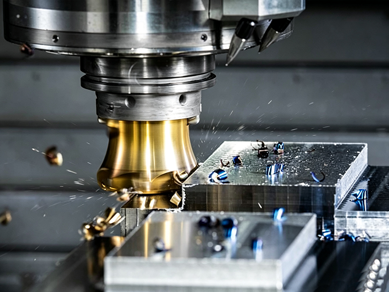
One clarification the peripheral milling definition usually needs: the name refers to *where on the tool the cutting happens*, not to machining “around the periphery of a part.” An end mill cutting the outside contour of a plate and a slab cutter facing a wide surface are both peripheral milling operations.
Ⅱ. How Does Peripheral Milling Work?
A complete peripheral milling operation runs through a fixed sequence:
1. Setup and datums. The workpiece is clamped, and the reference surfaces that will define part zero are established.
2. Tool selection. The feature — wall, slot, step, or profile — determines whether an end mill, cylindrical slab cutter, or side cutter is used.
3. Parameter setting. Spindle speed, feed rate, and depth of cut are set from the tool-material combination, not from a universal table.
4. Cutting. Each peripheral tooth enters the material, forms a chip, and exits in turn.
5. Chip evacuation. Chips must clear the cut; in full-slot conditions they need help from coolant, air, or toolpath design.
6. Verification. Profile dimensions, wall position, and surface quality are checked against the drawing.
The parameters that govern the process:
| Parameter | What it controls |
|---|---|
| Cutting speed | Tool life, heat, and surface condition |
| Feed per tooth | Chip load, cutting force, and finish |
| Axial depth of cut | Material removed per pass, tool load |
| Radial width of cut | Engagement between tool and wall |
| Cutter engagement | Heat concentration and deflection risk |
| Tool overhang | Rigidity and chatter tendency |
| Machine and fixture rigidity | Achievable accuracy and stability |
No fixed parameter set works for all materials — a steel slot and an aluminum wall demand different speeds, feeds, and engagement strategies, and tool manufacturers’ data should set the starting point.
Ⅲ. Main Types of Peripheral Milling
Slab Milling
Slab milling uses a wide cylindrical cutter to machine broad flat surfaces, classically on horizontal milling machines with the cutter on a long arbor. Because the cutting happens on the cylinder’s circumference with the axis parallel to the generated surface, it is peripheral milling in its original form. Modern vertical CNC machines have largely replaced it for flat surfaces, but it still appears on heavy, wide cuts where arbor-mounted cutters are economical.
Side Milling
Side milling machines the sides of a workpiece, steps, and narrow flat surfaces, using cutters that cut on both the periphery and the side faces. The circumference teeth do the primary work while the side teeth can finish a shoulder in the same pass. It suits features where a vertical surface and an adjacent step must be produced together.
Slot Milling
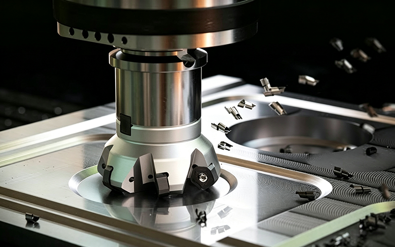
Slot milling cuts grooves, keyways, and parting features, with the cutter typically engaging its full circumference. Full-width slotting — plunging a cutter to depth and cutting a channel the same width as the tool — is the most demanding variant, because chips must escape a closed space while the tool is buried in material. Trimming the sides of an existing slot engages only part of the circumference and behaves more like profiling.
Straddle Milling
Straddle milling spaces two side cutters on one arbor so both sides of a workpiece are machined simultaneously. When two parallel surfaces must hold a specific relationship — the width of a boss, for instance — cutting both in one setup with one feed eliminates the tolerance stack a second setup would add.
Profile and Peripheral End Milling
Profile milling with end mills is the modern CNC expression of peripheral milling: the tool’s side flute length machines contours, walls, and pockets under programmed multi-axis control. Unlike slab milling, an end mill in a CNC spindle can follow any programmed contour, change effective engagement dynamically, and combine roughing and finishing in one tool. These peripheral milling types share one principle — cutting on the circumference — executed with very different equipment.
Ⅳ. Climb vs Conventional Peripheral Milling
In climb milling (also called down milling) the cutter rotation and feed direction agree at the point of contact; in conventional milling (up milling) they oppose. The choice changes chip formation, finish, and machine requirements:or a complete comparison of chip formation, cutting forces, machine requirements, and suitable applications, see climb milling vs conventional milling.
| Factor | Climb Milling | Conventional Milling |
|---|---|---|
| Rotation vs feed | Same direction at contact | Opposed direction at contact |
| Chip thickness | Thick entry, thin exit | Thin entry, thick exit |
| Surface behavior | Generally more stable | May rub before cutting |
| Backlash sensitivity | Requires a tight machine | Safer on worn manual machines |
| CNC practice | Preferred default | Used for specific conditions |
Climb milling is not universally better. On machines with backlash in the leadscrews, climb cutting can pull the workpiece into the cutter; on hard or scaled workpiece surfaces, conventional entry can be gentler on the tool. Fixture rigidity, workpiece skin condition, and the tool manufacturer’s recommendation all belong in the decision.
Ⅴ. Peripheral Milling Cutters and Tool Selection
The cutter families that perform peripheral cutting:
- Plain or slab milling cutters — cylindrical, straight or helical teeth, for wide flat cuts
- Side-and-face cutters — circumferential teeth plus side teeth, for steps and slots
- End mills — the general-purpose peripheral tool for profiles, walls, and pockets
- Roughing end mills — serrated teeth that break chips and cut with less heat and force
- Indexable cutters — replaceable inserts for high-volume roughing
- Solid-carbide cutters — small-diameter precision work where rigidity per size matters
| Machining feature | Suitable cutter |
|---|---|
| Wide surface on a horizontal mill | Slab cutter |
| Slot or narrow channel | Side-and-face cutter or end mill |
| External profile | End mill |
| Deep side wall | Long-reach end mill with controlled engagement |
| High-volume roughing | Indexable or roughing cutter |
| Precision finishing | Finishing end mill with appropriate geometry |
Selection depends on workpiece material, slot width or wall height, cutter diameter and flute length, overhang, roughing versus finishing duty, chip evacuation space, and machine power and rigidity. No cutter in the table is the only option for its row — geometry, access, and machine constraints routinely shift the answer.
Ⅵ. Face Milling vs Peripheral Milling
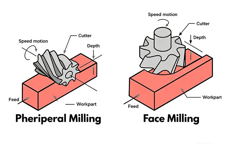
Face milling and peripheral milling differ in which part of the tool does the work, and the difference runs through every practical consequence:
| Factor | Face Milling | Peripheral Milling |
|---|---|---|
| Cutter axis | Usually perpendicular to generated surface | Usually parallel to generated surface |
| Main cutting edges | Face, corner, and periphery near the tip | Circumference or side flutes |
| Best suited for | Broad flats, datum surfaces | Walls, profiles, slots, steps |
| Dominant force tendency | Axial component more pronounced | Radial component more pronounced |
| Common cutters | Face mills, shell mills | End mills, slab mills, side mills |
| Typical accuracy task | Flatness, parallelism, face height | Profile dimensions, slot width, wall position |
| Main deflection concern | Spindle, workpiece, fixture stability | Tool deflection and thin-wall distortion |
The selection logic follows the geometry:
- Large flat surfaces and datum faces — face milling.
- External contours, walls, slots, and shoulders — peripheral milling.
- Complex CNC parts — usually both, in sequenced or combined toolpaths.
Neither process is inherently more accurate; they control different features. Face milling is judged on flatness and parallelism of a surface, peripheral milling on the position, width, and form of a wall or slot. The peripheral milling vs face milling question is answered by what the drawing calls out — a difference in controlled feature, not a difference in quality.
Ⅶ. Peripheral Milling vs End Milling
This pair is where most explanations blur two categories. Peripheral milling is a *cutting method* — an operation classified by which edges engage the material. An end mill is a *tool*. The two overlap without being the same thing.
An end mill cutting a profile with its side flutes is performing peripheral milling. The same end mill plunging or finishing a floor with its end teeth is performing something closer to face milling. A slab cutter performs peripheral milling without being an end mill at all.
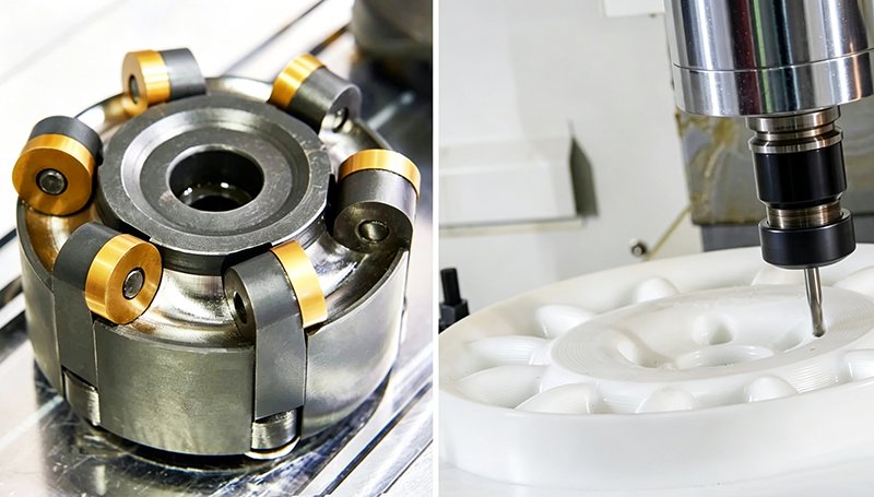
So “peripheral milling vs end milling” is not a versus question — one names the operation, the other names the tool most likely to execute it on a CNC machine. Keeping the categories separate prevents the common error of treating every end mill operation as if the side flutes were doing the cutting.
Ⅷ. Common Applications
Peripheral milling appears wherever parts carry side-oriented features:
- External profiles and contours
- Vertical walls and pocket walls
- Shoulders and steps
- Slots, grooves, and keyways
- Long edges and parallel side features
- Contoured side surfaces on brackets, plates, housings, and machine components
A single aluminum housing typically uses both processes in sequence: a face mill establishes the flat datum, peripheral milling with an end mill machines the outer contour, walls, and pockets, and a finishing pass holds the critical dimensions before inspection.
Ⅸ. Advantages and Limitations
Advantages:
- The natural route for walls, profiles, slots, and stepped features
- Long side flutes spread wear across more cutting edge
- Handles straight and contoured geometry under the same principle
- Works for both roughing and finishing
- Integrates directly into modern CNC toolpaths
Limitations:
- Radial forces deflect the cutter and can tilt walls
- Deep walls invite chatter and taper
- Long tool overhang cuts rigidity fast
- Full-slot conditions concentrate heat and make chip evacuation difficult
- Thin walls distort under radial load and residual stress
Ⅹ. Common Problems and Practical Solutions
| Problem | Likely cause | Possible action |
|---|---|---|
| Chatter | Excessive overhang or low system rigidity | Shorten overhang, improve fixturing, adjust engagement |
| Tapered wall | Tool deflection under radial load | Split roughing/finishing, reduce radial engagement |
| Poor finish | Worn tool, vibration, wrong parameters | Inspect tool, revisit speeds/feeds, leave finishing stock |
| Chip recutting | Insufficient evacuation | Improve coolant or air blast, rethink toolpath |
| Thin-wall distortion | Radial force and residual stress | Machine symmetrically, remove material in stages |
| Burrs | Tool condition or exit path | Optimize exit strategy, tool sharpness, deburr plan |
XI. How to Choose the Right Milling Strategy
Work through the decision in order:
1. Decide whether the feature to generate is a surface or a side — that alone picks the primary process.
2. Define the dimensional, flatness, or profile requirements the drawing actually states.
3. Check tool reach and access for every wall and slot.
4. Assess wall thickness and part rigidity — thin walls change the whole strategy.
5. Match the material to a cutter and coating combination.
6. Compare cycle time and tool changes across candidate strategies.
7. Plan roughing, semi-finishing, and finishing passes.
8. Confirm how each critical dimension will be measured.
When you hand CAD to a supplier, a few annotations decide whether the quote you get back is useful:
- Mark the critical datums, not every surface.
- Distinguish the critical faces from the critical walls.
- Identify the dimensions that actually control assembly.
- Don’t apply tight requirements to surfaces that don’t need them — cost follows them.
- Let the manufacturer combine both processes as the geometry requires.
Conclusion
The milling strategy follows the feature: face milling for broad flats and datum surfaces, peripheral milling for walls, profiles, slots, and steps, and the two combined wherever a CNC part carries both. Choose by what the drawing calls out — flatness for a face, position and width for a wall — and by tool access, rigidity, and the material in the cut.
If you are unsure which milling strategy is suitable for a critical surface, wall, slot, or profile, upload your CAD drawing to keywin for a manufacturability review and machining quotation.
FAQ
1. Is peripheral milling the same as slab milling?
Slab milling is one form of peripheral milling — a wide cylindrical cutter machining a flat surface with its circumference. Peripheral milling as a category also includes side milling, slot milling, straddle milling, and profile milling with end mills. The two are related but not interchangeable: a horizontal-mill slab cut and a CNC end-mill profile cut both rely on peripheral cutting edges, but they live in different equipment classes and remain distinct sub-types within the peripheral family.
2. Is peripheral milling the same as end milling?
No — the terms belong to different categories. Peripheral milling describes a cutting method defined by which tool edges engage the material. End milling describes a tool and its use. An end mill performing peripheral cuts with its side flutes is doing peripheral milling; using its end teeth to face a floor is closer to face milling. Keeping the categories separate prevents the common error of treating every end mill operation as if the side flutes were doing the cutting.
3. Can an end mill perform peripheral milling?
Yes — it is the most common form on CNC machines. Whenever an end mill machines a profile, wall, or pocket side with its peripheral flutes, the operation is peripheral milling. The tool category and the cutting method simply intersect here. A 6 mm end mill in an aluminum bracket and a 25 mm roughing end mill in a steel pocket both cut peripherally when the side flutes are engaged, even though the engagement ratio, chip load, and finishing strategy look different at each scale.
4. Which is better, face milling or peripheral milling?
Neither is universally better; they generate different features. Face milling suits broad flat and datum surfaces where flatness and parallelism govern. Peripheral milling suits walls, slots, profiles, and shoulders where position, width, and form govern. The choice follows the geometry — a thin-wall aerospace bracket with a critical surface and a critical contour will likely use face milling for the datum and peripheral milling for the walls in the same cycle.
5. What is the main cutting force concern in peripheral milling?
Radial load. Because cutting forces act perpendicular to the tool axis, they deflect the cutter, tilt walls into taper, excite chatter on deep walls, and distort thin sections. Controlling overhang, engagement, and pass strategy manages all of these failure modes — a 6×D reach and a 1.5×D reach behave very differently in the same wall, even with identical speeds and feeds, and the rules change again when the part is aluminum versus hard steel.
6. Can face milling and peripheral milling be used on the same part?
Yes, and in CNC machining it is the norm rather than the exception. A typical cycle faces the datum surface, then machines contours and walls peripherally, then finishes critical dimensions — all in one or two setups. The combined approach lets a manufacturer hold both flatness on the reference face and positional accuracy on the walls without re-fixturing, which is why most multi-feature parts specify both processes in their manufacturing routing.