
Ⅰ. Introduction
A blind hole is a hole or passage that is closed at one end and does not penetrate the entire object; as one of the most fundamental hole types in mechanical engineering, it is widely used in aerospace, automotive manufacturing, electronics, electrical engineering, and medical device industries. Its core value lies in providing sealing, positioning, and connection functions while maintaining the structural integrity of the workpiece. This article will explain the basics of blind holes to help you understand the key considerations when designing and machining them.
Ⅱ.What Is a Blind Hole?
A blind hole is a hole that does not pass completely through a material. Based on their geometry, blind holes can be classified into flat-bottomed, round-bottomed, and stepped types. Unlike through-holes, blind holes retain the material on the reverse side of the workpiece, thereby creating a completely enclosed cavity; their primary value lies in preserving the continuity and integrity of the workpiece’s external surface. In engineering applications, they primarily serve functions such as fastening connections, fluid sealing, and structural support.

Ⅲ. Characteristics Of Blind Hole
Structural Characteristics
- Open on one side, closed at the bottom
A blind hole opens on only one side and does not pass through the entire material; structurally, it differs fundamentally from a through-hole.
- Limited depth and non-penetrating
The depth of a blind hole is less than the thickness of the workpiece, terminating within the material.
- The bottom features a specific geometric form
Typically, a conical bottom is formed through drilling; however, a flat-bottomed structure can also be achieved through milling.
Functional Characteristics
- Maintain structural integrity
Since they do not penetrate the material, blind holes do not compromise the structural integrity of the reverse side, thereby helping to maintain the overall rigidity of the workpiece.
- Ensure excellent sealing performance
Suitable for applications with high sealing requirements, such as pneumatic control ports, hydraulic systems, and similar scenarios.
- Enhance space utilization
Achieving functional structures within a limited space facilitates compact design and optimizes product layout.
Ⅳ. In What Areas Are Blind Holes Used?
Blind holes are widely used across various industries:
Mechanical Connection and Fastening
- Threaded holes: This is the most common application. By machining threads in blind holes, components can be fixed without the use of nuts, ensuring a firm connection and a clean appearance with no protrusions on the back.
Electronics and Electrical Engineering
- Battery Housing: Employs a blind-hole structure to seal port locations, avoiding through-holes in the housing and effectively preventing liquid leakage and dust ingress.
- Connector Mounting Holes: Securely anchor electronic connectors, maintain internal sealing, and prevent moisture and impurities from compromising electrical performance.
Aerospace
- Sealed Oil Circuit Structure: Blind holes are machined into components of the fuel and lubrication systems to accommodate seals and secure pipeline interfaces, thereby preventing media leakage that could result from through-holes.
- Sensor Mounting Holes: Blind holes serve as the mounting datum for sensors, ensuring precise positioning while preventing the holes from penetrating the component; this safeguards against internal media leakage within the aerospace equipment and prevents the ingress of external contaminants.
Medical Devices
- Implant fixation: such as the threaded holes of orthopedic screws
- Precision positioning: the positioning structure of surgical instruments
Daily Necessities
- Furniture Assembly: Creating blind holes in furniture components to ensure a seamless exterior appearance with concealed connections.
- Eyeglass Frames: Creating hinge mounting holes for a more aesthetically pleasing and lightweight design.
Ⅴ. Advantage And Disadvantages Of Blind Holes
Advantages of Blind Holes
- Sealing and Leak Prevention
The closed-bottom structure forms a sealed chamber, effectively preventing liquid or gas leakage.
- Maintaining Aesthetic and Structural Integrity
Since the hole does not penetrate the workpiece, it avoids the need for a back-side opening, enhancing overall aesthetics and structural integrity.
- Improved Structural Strength and Stability
Compared to through holes, blind holes cause less weakening of the material cross-section, helping to maintain the workpiece’s strength
- Supports integrated functional design
Multiple functions—such as stepped structures, threads, and storage—can be incorporated into a single hole, reducing machining operations and the number of required holes.
- Optimizes assembly and positioning
Serves as an axial positioning reference while controlling the effective length of threads, thereby reducing assembly risks and the likelihood of tool damage.
- Supports lubrication and sealant storage
Allows for the pre-storage of grease or adhesives, reducing the frequency of maintenance and extending the service life of parts.
Disadvantages of Blind Holes
- Difficult chip evacuation and susceptibility to clogging at the bottom of the hole
Chips cannot be discharged naturally, requiring frequent tool retraction and affecting machining efficiency.
- High machining difficulty and strict process requirements
Cutting conditions at the bottom of the tool are poor, making it prone to wear or breakage; this places high demands on machine accuracy and programming.
- High risk of dimensional control
Once the depth exceeds tolerance, it is often impossible to correct, which can easily result in the entire part being scrapped.
- Difficult inspection and maintenance
Internal defects are difficult to detect, and the cost of subsequent repairs is high.
- Poor heat dissipation, prone to heat buildup
The enclosed structure restricts heat dissipation pathways, which may affect machining stability and part performance.
- Prominent stress issues
Stress concentration is likely to occur at the bottom of the hole, and residual stress is difficult to release; long-term use may lead to fatigue issues.
- Limited clamping and positioning
Auxiliary positioning from the back is not possible, resulting in low flexibility in machining and assembly.
Ⅵ. How to Interpret Blind Holes On Engineering Paper?
As a newly minted engineer—or perhaps a purchasing specialist or product manager who needs to interpret technical drawings—you may find yourself completely bewildered the first time you encounter a blind hole annotation; faced with a combination of letters, numbers, and symbols, it is often difficult to know where to begin. This chapter will guide you through a three-step process to decipher blind hole annotations on engineering drawings: View Identification → Symbol Interpretation → Dimension Analysis.
The First Step :View Identification
Once you have the drawings, first determine what information each of the three types of views represents:
- The principal view typically employs a sectional view to illustrate the internal structure of the hole; particular attention should be paid to the shape of the hole bottom: if it features a 120-degree cone angle (or a simplified pointed cone representation), this indicates a standard blind hole produced directly by a drill bit; conversely, if labeled “Flat Bottom” or depicted with a straight line at the base, it requires processing via a flat-bottom drill or milling—processes that entail different manufacturing steps and costs.
- The top view (or layout view) indicates the hole’s position using a circle intersected by cross-centerlines, with accompanying quantity symbols used to clearly define the distribution pattern of the holes.
- Detail views (local enlargements) are frequently provided for critical mating features; consequently, the dimensional tolerances and surface roughness specifications in these specific areas must be subject to rigorous verification.
The Second Step :Symbol Interpretation
Blind hole dimensions are categorized into two types: threaded blind holes and plain cylindrical blind holes. The notation for these two types differs significantly; please refer to the quick reference table below.
| Symbol / Notation | Meaning | Description and Examples |
|---|---|---|
Threaded blind holes | ||
n× |
Number of Holes |
e.g., 4× indicates four identical holes. |
M6 / M8×1 |
Thread Specification |
M + Nominal Diameter; for fine-pitch threads, the pitch must be specified (e.g., M8×1). |
6H/7H |
Internal Thread Precision |
The number indicates the tolerance grade, while H signifies a basic deviation of zero (H is designated for internal threads, and g/h for external threads). |
T10/ Deep 10 |
Effective Thread Depth |
The actual working length of the screw engagement, excluding the retraction space. |
Hole T12 / Drilling Depth 12 |
Total Depth of Pilot Hole |
The total length of the drilled hole, including the tapered bottom, is typically 2–5 mm longer than the thread depth to allow for tool retraction space. |
| Plain cylindrical blind holes | ||
|---|---|---|
Ø10×25 |
Diameter × Depth |
10 mm in diameter, 25 mm deep cylindrical section; “×” or “deep” indicates the depth |
Ø15×10/Ø10×25 |
Stepped Hole |
Sections separated by slashes; outer layer Ø15, depth 10; inner layer Ø10, depth 25. |
| Special Notation | |||
|---|---|---|---|
Flat |
Requires flat-bottom machining |
A flat-bottom drill or milling cutter must be used; it must not be treated as a standard conical bottom. If this annotation is absent, a conical bottom (approximately 120°) is assumed by default. | |
Component Sourcing and Fabrication |
Fit Machining |
Must be machined or measured together with its mating part; it cannot be finished independently. | |
C1/ Deburring |
Hole Chamfer |
“C” is followed by the chamfer dimension; deburring is a process requirement, and any sharp edges at the hole openings must be treated. |
The Third Step :Dimension Analysis
Depth is the most common source of error when interpreting blind holes, as the term “depth” carries three distinct meanings on technical drawings:
- Markings labeled “Depth” or “×” typically refer to the depth of the cylindrical section.
- Markings specifying “Drill Depth” include the total depth, encompassing the 120-degree conical tip.
- Markings specifying “Effective Depth” refer solely to the mating or threaded working section.
All three may appear simultaneously on a single drawing; they must be verified individually and cannot be used interchangeably.
Summary
When performing a comprehensive interpretation, first identify the categories and distribution of hole features; next, extract key dimensions—such as diameter and depth—and clarify the specific definition of the depth measurement; finally, verify tolerances, surface roughness requirements, and any special processing specifications. Three common errors warrant particular vigilance: mistaking the cylindrical depth for the total drilling depth, which results in an undersized pilot hole; overlooking the thread relief space, which causes damage to the tap tip or the hole bottom during the tapping operation; and assuming—solely based on the presence of a conical bottom—that a flat-bottom finishing process is unnecessary, despite the drawing specifying otherwise.
e.g.:
Next, utilizing the aforementioned method—and combining both diagrams and text—I will interpret the blind holes depicted on the engineering drawing.
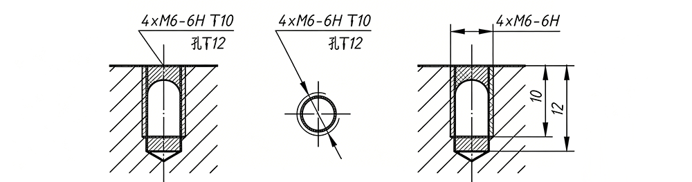
The accompanying figure presents three views of the same blind hole: a front view on the left, a top view in the center, and a detailed dimensioned view on the right; together, these three views comprehensively illustrate the hole’s structure, dimensions, and position.
Symbol Interpretation: The annotation “4×M6-6H” can be broken down as follows: 4 identical holes (4×); a standard thread with a nominal diameter of 6 mm (M6); and an internal thread tolerance zone of 6H (representing Grade 6 precision, where “H” indicates a basic deviation of zero).
Key Dimensional Relationships:
The detailed view on the right provides two depth values:
- T10 indicates an effective thread depth of 10 mm—specifically, the actual working length where the screw engages and threads into the hole;
- Hole T12 indicates a total pilot hole depth of 12 mm. (Hole: Drilled Hole / Pilot Hole)
The 2 mm difference between the total hole depth and the thread depth is critical: it ensures sufficient clearance for the tap, preventing it from bottoming out, while simultaneously avoiding excessive drilling depth that could compromise the structural integrity of the workpiece.
Structural Interpretation:
The diagram depicts the hole bottom using a simplified conical symbol, indicating that it is a blind hole (i.e., it does not pass through the workpiece). Unless otherwise specified, the hole bottom is assumed to be the result of a standard drilling operation, resulting in an approximate 120° conical tip. Furthermore, the absence of a “Flat Bottom” annotation implies that the hole is to be produced via standard drilling; no additional flattening operation is required.
Ⅶ. Key Design Considerations For Blind Holes
- Difficult Chip Evacuation: Chips tend to accumulate at the bottom of the hole, leading to scratches on the hole walls, tool breakage, or inaccurate drilling results.
- Poor Heat Dissipation: Blind holes constitute a confined space; the heat generated during the cutting process becomes trapped, resulting in thermal accumulation.
- Challenging Inspection: The bottom of the hole is not visible, making measurement inconvenient and precluding real-time monitoring of drilling depth; furthermore, the drill bit is prone to deviating from the central axis, resulting in compromised positional accuracy.
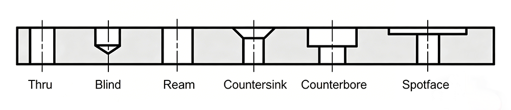
Ⅷ . Comparison Of Blind Hole And Other Types
| Type | Structure | Machinability | Core Functions | Typical Applications |
|---|---|---|---|---|
Blind-hole |
Open on one side, closed at the bottom. |
In the middle, basic processing |
Okay, a sealed cavity can be formed. |
Threaded hole, air chamber, locating pin |
Through-hole |
Fully penetrating, with openings on both sides |
Low, basic processing |
Poor; it fails to form an enclosed space. |
Bolted connection, weight reduction, wiring |
Ream |
High-Precision Cylindrical Hole |
Through hole or blind hole finishing |
Precision Fit |
Locating pin hole, bearing housing |
Countersink |
Inverted cone at the top; through-hole or blind hole at the bottom. |
Mouth reprocessing |
Accommodates countersunk screws |
Countersinking and Deburring of Screws |
Counterbore |
The upper part has a large diameter and a flat bottom, and the lower part has a small diameter extending |
Mouth reprocessing |
Accommodating bolt heads or bearings |
Concealed bolt heads, bearing installation |
Spotface |
Local Spot-facing of Boss Around Hole |
Mouth reprocessing |
Provide a flat support surface |
Improve Assembly Contact and Gaskets |
Ⅸ .Conclusion
In CNC machining, the sealed configuration of blind holes offers distinct advantages: reliable sealing, structural integrity, and a clean aesthetic. Consequently, it effectively meets the requirements of precision machinery, fluid control systems, and products with stringent aesthetic standards. However, these benefits are predicated upon sound design principles—specifically, the fact that the inherent machining complexity cannot be overlooked. During the design phase, it is essential to strike a balance between functional objectives and manufacturing feasibility; only by judiciously managing the depth-to-diameter ratio and ensuring adequate conditions for chip evacuation and cooling can the true value of blind holes be fully realized.
Ⅹ. FAQ
Q: What is the standard depth-to-diameter ratio for blind holes?
There is no single, universally standardized ratio for depth and diameter; however, established empirical limits do exist. A depth-to-diameter ratio of 3:1 or less is considered standard machining; a ratio between 3:1 and 5:1 falls under the category of deep-hole machining, requiring measures such as internal cooling or intermittent tool retraction.
Ratios exceeding 5:1 significantly increase machining difficulty and necessitate the use of specialized deep-hole equipment. Consequently, during the design phase, it is advisable to keep this ratio within the 5:1 limit.
Q: Can blind holes be tapped?
Yes, blind holes can be tapped, provided that two specific conditions are met:
- Allow for tool retraction clearance: The drilled depth of the hole must exceed the required thread depth by an additional 1 to 1.5 times the thread pitch. This prevents the tap from bottoming out against the base of the hole and breaking.
- Facilitate chip evacuation:Employ spiral-flute taps or utilize internal cooling methods to ensure that chips are expelled upward out of the hole. If insufficient clearance is provided for tool retraction, the tap is highly susceptible to breakage and becoming scrapped.
Q: Difference Between Blind Holes and Through Holes?
A blind hole is open on one side but closed at the bottom; it presents significant manufacturing challenges, requiring precise control over depth and chip evacuation. However, it allows for the creation of a sealed cavity, preserves the integrity and aesthetic appeal of the reverse side, and offers superior structural strength.
A through hole penetrates the material completely; it is simple to machine, and chips are easily evacuated. Conversely, it cannot form a sealed cavity, it reduces the cross-sectional strength of the material, and the hole remains exposed on the reverse side.
Q: How to Determine Whether Your Design Requires a Blind Hole or a Through Hole?
The choice should be based on functional requirements.
If the design necessitates creating a sealed space, maintaining the integrity of the reverse side, or preserving structural strength, consider using a blind hole.
If the requirement is merely for a continuous connection, weight reduction, or cable routing, opt directly for a through hole.
In summary: for simple connections, low-budget projects, or the absence of special requirements, choose a through hole; however, if aesthetic appeal, specific connection strength, and sealing capabilities are required, choose a blind hole.
Q: Why Does Chip Evacuation Become a Problem with Blind Holes?
The bottom of a blind hole is closed, making it impossible to evacuate chips from the opposite end. If chips accumulate, they can easily damage the hole walls and the workpiece itself.
Furthermore, the buildup of heat accelerates tool wear and deformation, while cutting fluid struggles to reach the bottom of the hole, resulting in inadequate lubrication. Consequently, chip evacuation becomes a critical challenge in the machining of blind holes.