Lathe tooling is the cutting system mounted on a lathe or turning center to turn, face, groove, part, thread, and bore metal parts. A complete system has three levels: the tool post or turret interface that connects to the machine, the tool holders and boring bars that carry the cutting edge, and the insert or solid tool that actually removes material.
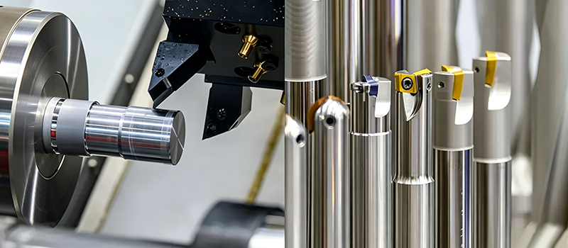
Selection shows up directly in part outcomes. The right lathe tools hold dimensional stability, surface finish, and chip control through a production run — and they set cycle time and tool life with them. The wrong combination produces chatter, burrs, stringy chips, and drifting dimensions long before anyone touches a speed dial. What follows is the tooling system, tool type by tool type, and the selection logic that matches tools for the lathe to the job on the machine.
Ⅰ. What Is Lathe Tooling?
Lathe tooling is the complete set of cutting components — tools, holders, and machine interfaces — that turns a rotating workpiece into a finished part. It splits into three levels.
Cutting Tool or Insert
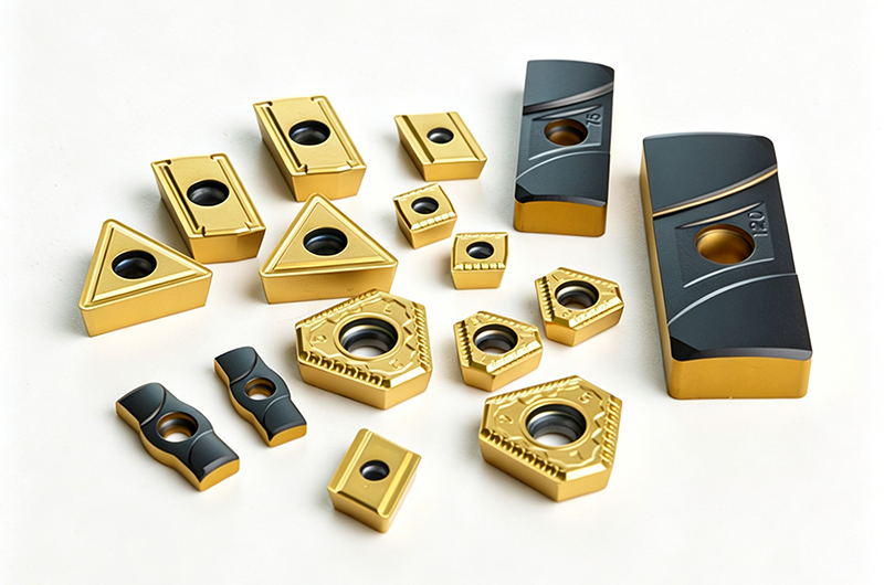
The insert or tool tip is the only part that touches the workpiece — usually an indexable carbide insert clamped to a holder in CNC work, or a solid HSS tool bit ground to shape on manual lathes.
Tool Holder, Shank, or Boring Bar
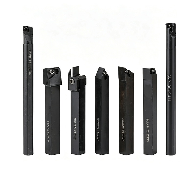
The holder clamps the insert and connects it to the machine; its shank size, style, and length set the rigidity and reach of the setup. A boring bar is the internal variant — a holder designed to reach inside an existing hole with as much diameter and support as the bore allows.
Tool Post or Turret Interface
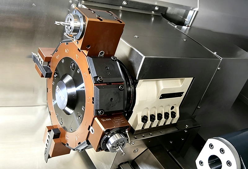
Manual lathes use a quick-change tool post that clamps square-shank tools at a repeatable height; CNC turning centers use a turret with standardized station bolt patterns, where each position repeats accurately. The interface decides which holders the machine accepts and how much setup rigidity carries through to the cut.
Turret / tool post → tool holder → insert → cutting edge → workpiece
(interface) (rigidity) (edge) (part)
Chucks, collets, tailstocks, and live centers are not cutting tools; they are workholding or support components that locate and stabilize the workpiece. They sit outside cutting-tool selection, but they remain part of the complete machining setup because workpiece support directly affects vibration, deflection, surface finish, and the cutting parameters the tooling can sustain.
Ⅱ. Main Types of Lathe Cutting Tools by Operation
Within the broader CNC turning process, lathe tools are best classified by the operation they perform rather than by their shape, brand, or holder style:
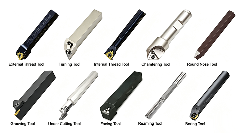
| Tool Type | Main Operation | Feature produced | Key selection concern |
|---|---|---|---|
| Turning tool | OD roughing/finishing | External diameters and profiles | Insert geometry and nose radius |
| Facing tool | Facing | Flat end face | Feed direction and clearance |
| Boring bar | Internal turning | Bores and internal profiles | Overhang and rigidity |
| Grooving tool | Grooving | External/internal grooves | Groove width and chip evacuation |
| Parting tool | Cutoff | Separates completed part | Blade width and stability |
| Threading tool | Thread turning | Internal/external threads | Thread form and pitch |
| Form/profile tool | Profiling | Contours and special forms | Cutting load and tool geometry |
| Knurling tool | Forming rather than cutting | Textured surface | Pattern, pitch and pressure |
External Turning Tools
External turning removes material from the outside diameter — the default lathe operation. Rough turning prioritizes material removal: a strong edge, larger nose radius, deeper cuts. Finish turning prioritizes surface quality and accuracy: a sharper edge, controlled feed, lighter depth. Profiling tools use a triangular or diamond insert whose included angle reaches into contours and shoulders.
Right-hand and left-hand describe the tool’s cutting-edge orientation and intended feed direction, not simply which side of the part is being machined. In conventional front-tool-post terminology, a right-hand tool normally cuts while feeding from the tailstock toward the headstock, and a left-hand tool works in the opposite direction. Rear turrets, inverted tooling, spindle direction, and machine configuration can change how this appears in practice, so holder orientation should always be verified on the actual machine.
Facing Tools
Facing cuts a flat end surface perpendicular to the part axis. A facing tool is structurally close to a turning tool, but the tip must register accurately on center height — otherwise an uncut nub can remain at the center of the face.
Feed typically runs from the outer diameter toward the center. As the tool approaches center, the effective cutting speed drops, so chip formation and surface quality in that region deserve close attention.
Boring Bars
Boring enlarges, corrects, or finishes a hole that already exists — the same distinction that separates boring from drilling.
Stability is dominated by bar overhang. The longer the unsupported bar, the lower its stiffness and the higher the risk of vibration and chatter. Within the limits of the bore, use the largest bar diameter available, keep overhang as short as possible, select a favorable insert geometry, and ensure adequate coolant at the cutting zone.
For deep holes and high length-to-diameter ratios, depth, surface quality, and roundness have to be balanced. Anti-vibration bars and carbide-reinforced bars earn their place when reach and rigidity are pushed to the limit.
Grooving and Parting Tools
Grooving tools cut grooves of a defined width and depth — O-ring grooves, relief grooves, snap-ring grooves. Parting (cut-off) tools plunge radially through the part to separate the finished workpiece from the stock.
In parting, the blade has to feed continuously toward the center, so blade width, center height, tool rigidity, and workpiece support all affect stability directly. Grooving and parting share a common constraint — chip evacuation. If chips cannot clear, they pack into the narrow groove, causing vibration, surface damage, and edge chipping.
Some holder systems accept both grooving and parting inserts, but the two operations differ in cutting depth, insert geometry, and stability requirements and cannot be treated as the same process.
Threading Tools
Threading tools cut external or internal threads; the insert profile must match the target thread form and pitch. During cutting, the tool advances one pitch per spindle revolution, with multiple synchronized passes forming the complete thread.
Threading is sensitive to insert condition, tool positioning, and infeed strategy — each of which influences thread profile, dimensional accuracy, and final fit.
Full-profile inserts cut the complete form — crest and root — for a specific pitch. Partial-profile inserts cover a range of pitches with greater flexibility, but cannot fully form the crest profile the way a full-profile insert can.
Forming, Chamfering, and Knurling Tools
Form tools use a pre-shaped cutting edge to produce arcs, tapers, or other specific profiles in a single pass — reducing the number of cuts but increasing contact area and cutting force, which raises the demand on workholding and machine rigidity.
Chamfering tools break sharp edges or cut a specified lead-in angle. In practice, chamfering is often integrated into turning, facing, or other turning tools to reduce tool changes and handling.
Knurling tools differ from the cutting tools above. Knurling presses rollers against the workpiece to plastically displace material and raise a regular pattern; it does not remove material by cutting. The radial forces involved are large enough that stick-out, rigidity, and workholding stability all matter.
Ⅲ. Lathe Tooling Materials: HSS vs Carbide and Other Options
| Tool Material | Strength | Limitations | Typical Use |
|---|---|---|---|
| HSS | Tough, inexpensive, easy to grind | Lower hot hardness and cutting speed | Manual lathes, interrupted or special-profile work |
| Carbide | Higher speed, wear resistance, replaceable inserts | More brittle and requires stable setup | Most CNC production turning |
| Ceramic | High-temperature cutting ability | Brittle; application-specific | Hardened materials and selected cast irons |
| CBN | Excellent for hardened ferrous materials | High cost and limited application range | Hard turning and finishing |
| PCD | Excellent wear resistance on nonferrous/abrasive materials | Generally unsuitable for ferrous materials at high temperature | Aluminum, copper alloys, composites |
HSS Lathe Tools
HSS lathe tools remain the practical choice on manual machines: tough, cheap, easy to regrind, tolerant of interrupted cuts and imperfect setups, and groundable into any special profile. The trade is hot hardness — cutting speeds stay well below carbide territory. HSS is not a soft-aluminum-only material; it machines steels and stainless competently at manual and low-production speeds.
Carbide Lathe Tools
Carbide lathe tools come in two constructions. Brazed tools have a carbide tip on a steel shank — cheaper, resharpenable a limited number of times, common on general-purpose lathes. Indexable inserts clamp into holders and rotate through multiple edges: the production standard for CNC turning.
Carbide only outperforms HSS when the system cooperates. Grade, coating, and geometry must match the workpiece material, and carbide’s lower toughness means an interrupted cut or unstable setup can chip an edge where HSS would survive. It is the right default for CNC production turning, not an automatic upgrade everywhere.
Ceramic, CBN, and PCD
Ceramic inserts cut at high temperature in hardened materials and selected cast irons, but are brittle and application-specific. CBN excels at hard turning and finishing hardened ferrous parts, within a narrow and expensive range. PCD delivers outstanding wear resistance on aluminum, copper alloys, and abrasive nonferrous materials — and is generally unsuitable for ferrous work at elevated temperature. In every case the cutting data comes from the tool manufacturer’s grade-specific documentation, matched to the exact material condition; none of these materials is a blanket recommendation for a class like titanium or hardened steel.
Ⅳ. Understanding Inserts and Tool Holders
Indexable Inserts
An insert is specified by shape, clearance angle, tolerance class, size, thickness, nose radius, chip breaker geometry, and grade or coating. ISO 1832 defines the identification code (check the current edition of the standard directly), and a code such as CNMG 120408 decodes as:
C N M G 12 04 08
│ │ │ │ │ │ └─ nose radius 0.8 mm
│ │ │ │ │ └───── thickness code
│ │ │ │ └────────── size (cutting edge length) code
│ │ │ └────────────── tolerance class M
│ │ └────────────────── clearance angle 0°
└─────────────────────────── rhombic 80° shape
Each property is a selection lever. Shape sets edge strength against contour access; nose radius trades theoretical finish against radial force; the chip breaker decides whether chips form, curl, and break at your actual feed and depth of cut.
Tool Holders
The holder positions and supports the insert, and controls five things: insert location accuracy, rigidity, reach to the feature, coolant delivery to the cutting zone, and overhang. Turret or tool-post compatibility is a hard constraint — a lathe tool holder that does not match the machine’s station pattern or size cannot be used at all.
Why Tool Overhang Matters
Overhang is the cheapest tooling problem to fix and one of the most common causes of chatter. Stiffness falls off steeply as unsupported length grows, so the working rule is simple: the shortest overhang that reaches the feature. No universal maximum length-to-diameter ratio is valid — the safe limit depends on bar construction, insert geometry, and cutting conditions.
Short overhang: ▐██▌──────── stiff — stable cut
Excessive: ▐██▌────────────── deflection — chatter marks
For internal work, favor the largest boring bar diameter that clears the bore and the shortest reach that completes it. If vibration persists, the fixes in order: shorten the bar, increase its diameter, switch to an anti-vibration bar, reduce depth of cut, change insert geometry.
Ⅴ. How to Choose the Right Lathe Tooling
Step 1 — Identify the Turning Operation
Start with the operation: external turning, facing, boring, grooving, parting, threading, or profiling. The operation selects the tool family; every later decision narrows within it.
Step 2 — Check the Workpiece Material
Aluminum, carbon and alloy steels, stainless steel, brass and copper, cast iron, titanium, hardened steel, and engineering plastics each favor different insert grades, coatings, and geometries. Material condition — hardened, solution-treated, free-machining — shifts the choice as much as the alloy family. Speeds and feeds should come from the tool manufacturer’s data for the specific grade; generic cutting-speed tables ignore too many variables to trust in production.
Step 3 — Define Roughing or Finishing
| Requirement | Roughing tendency | Finishing tendency |
|---|---|---|
| Material removal | Higher | Lower |
| Edge strength | More important | Sharpness and stability more important |
| Nose radius | Often larger, subject to stability | Selected according to finish and vibration risk |
| Feed/depth | Higher | Lower and controlled |
| Main goal | Productivity | Accuracy and surface quality |
One caution on nose radius: a larger radius improves the theoretical finish at a given feed, but also increases radial cutting force. On slender parts or marginally rigid setups, the vibration it induces is worse than the finish it promises. Nose radius balances finish, edge strength, and vibration risk — it is not a “bigger is better” parameter.
Step 4 — Check Machine Power, Rigidity, and Workholding
Tooling selection is a machine-limited decision. Spindle power caps depth and feed. Machine rigidity and workholding decide how aggressively a cut can run before it chatters. Part stick-out turns cutting force into deflection, and turret or tool-post compatibility determines which holders are usable at all. A heavy roughing insert on an underpowered or flexible setup does not remove more material — it stalls, chatters, or breaks.
Step 5 — Match Tolerance, Surface Finish, and Chip Control
The final tooling decision must match the part’s quality requirements. Tighter tolerances and surface-finish requirements need predictable wear behavior, stable holder positioning, and consistent cutting edges. A specified Ra value influences nose radius, feed, edge preparation, and finishing strategy. Chip control can become the deciding constraint: if the chip breaker does not work within the actual feed and depth-of-cut range, long chips can wrap around the workpiece, damage finished surfaces, and interrupt unattended production. Burr formation and dimensional drift should likewise be evaluated through insert geometry, grade, edge condition, and wear trends.
Ⅵ. Common Lathe Tooling Problems and What They Indicate
| Problem | Likely tooling-related causes | What to check |
|---|---|---|
| Chatter | Excessive overhang, weak holder, unsuitable nose radius | Shorten setup, improve support, review geometry |
| Poor surface finish | Worn edge, built-up edge, unstable setup | Insert condition, speed/feed, rigidity |
| Long uncontrolled chips | Wrong chip breaker or cutting conditions | Insert geometry, feed and depth of cut |
| Burrs | Dull edge or unsuitable geometry | Edge condition and tool path |
| Rapid tool wear | Wrong grade/coating or excessive heat | Workpiece material, cutting data and coolant |
| Dimensional drift | Wear, thermal change or holder movement | Tool offsets, clamping and inspection trend |
Chatter and poor finish usually trace to setup stiffness and geometry, not the tool’s brand. Wear and dimensional drift usually trace to grade, coating, and cutting data.
Ⅶ. How Lathe Tooling Affects Part Quality and Cost
- Cycle time depends on the balance between dedicated and multifunction tooling. Dedicated tools can optimize cutting conditions for individual operations, while multifunction tools may reduce tool changes and free valuable turret stations.
- Downtime follows tool management: unplanned insert changes and abnormal wear stop the spindle; scheduled edge changes do not.
- Rework and scrap follow quality: chatter marks, burrs, and drifted bores are tooling outcomes before they are inspection outcomes.
- Feature limits follow geometry: nose radius, reach, and minimum groove width decide which drawing features are manufacturable at all.
- Tool count follows the drawing: every feature family — internal grooves, deep bores, special threads — adds a tool and a tool change, and both appear in the quote.
- Special features cost more: complex internal grooves, deep bores, and non-standard threads need dedicated tooling or conservative parameters, and either path raises part cost.
Ⅷ. Lathe Tooling Selection Checklist
- What operation is required?
- What material and condition will be machined?
- Is the cut roughing, semi-finishing, or finishing?
- Is the operation external or internal?
- What tolerance and surface finish are required?
- Is the setup sufficiently rigid?
- What is the minimum required tool overhang?
- Is chip evacuation difficult?
- Are there narrow grooves, deep bores, small radii, or special threads?
- Is the holder compatible with the machine interface?
Conclusion
Lathe tooling is not a single tool choice — it is a system match. The operation selects the tool family, the material and its condition select the grade and coating, the tolerance and finish select the geometry, and the machine, workholding, and overhang decide what the cut can actually deliver. Treat insert, holder, and interface as one decision and dimensional stability, surface quality, chip control, cycle time, and tool life follow; treat them separately and no single purchase fixes the result.
If you need help manufacturing a turned component, upload your CAD model and drawing for a CNC turning quote. Keywin can review the part geometry, material, tolerances, surface-finish requirements, production quantity, and CNC turning strategy before machining begins.
Frequently Asked Questions
1. What is included in lathe tooling?
The cutting tools or indexable inserts, the lathe tool holders and boring bars that carry them, and the tool post or turret interface that connects the holders to the machine. Workholding — chucks, collets, centers — supports the part but is not part of the cutting system.
2. What are the most common lathe cutting tools?
Turning, facing, boring, grooving, parting, and threading tools cover the great majority of turning work, with form/profile and knurling tools added for contours and grip patterns.
3. What is the difference between HSS and carbide lathe tools?
HSS is tougher, cheaper, easy to regrind, and tolerates interrupted cuts and manual-speed work, but its hot hardness limits cutting speed. Carbide runs faster, wears slower, and is the production standard as indexable inserts — but it is more brittle and needs a stable setup.
4. How do I choose tools for the lathe?
Work through the operation, the workpiece material and condition, the roughing or finishing role, the machine’s power and rigidity, and the tolerance, finish, and chip control the part requires — the same sequence as the checklist.
5. What is the difference between a grooving tool and a parting tool?
A grooving tool forms a groove of specified width and depth; a parting tool plunges through the full diameter to separate the finished part from the stock. Some systems share hardware between the two, but blade width, strength, and chip evacuation requirements differ.
6. Are CNC lathe tools different from manual lathe tools?
The cutting principles are identical, but CNC work depends on standardized holders, indexable inserts, repeatable turret positioning, and stable documented cutting data — manual work leans more on ground HSS tooling and operator setup skill.