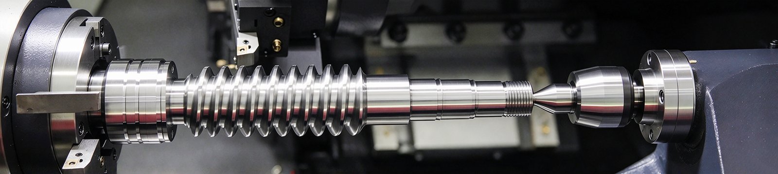
Ⅰ. What Is a Bevel in CNC Machining?
A bevel is an angled surface that replaces the sharp transition between two faces of a part. A bevel is defined by its angled planar geometry rather than a radius. In CNC machining, the practical bevel meaning is functional rather than decorative: that angled face may break a sharp edge, lead a mating part into position, open clearance for a weld or a fastener, or meet a surface requirement the drawing calls out. On a drawing, that geometry should be controlled with enough information to locate and size it clearly, such as an angle with a width, length, depth, or fully defined CAD geometry. The angle is whatever the drawing specifies, not an automatic 45°.
That distinction decides whether the part can be quoted. “Add bevel” with no angle, no width, and no location is not something a supplier can price or an inspector can check. The sections below cover how bevels are defined, how they differ from chamfers, what belongs in a callout, and where bevel geometry runs into manufacturing limits.
Ⅱ. The Bevel Definition for Machined Parts
Bevel vs. Radius: What Makes It a Bevel
A bevel is a flat angled face. Two adjacent surfaces meet it at a defined angle, and the face itself has a measurable width. A fillet is the opposite case: a rounded transition defined by a radius. A square edge has neither — the two surfaces simply meet at a corner.
That distinction is geometric, not semantic. If the callout carries an angle and a size dimension, the feature is an angled face. If it carries a radius, it is not a bevel, whatever word the drawing uses.
Where Bevels Appear on a Part
Bevels turn up in predictable places:
- Outer edges and perimeter faces, where a sharp corner is undesirable
- Hole entrances, where a pin, shaft, or bolt has to start cleanly
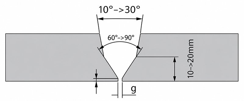
- Plate and wall edges that will be welded or joined later
- Mating faces that need clearance for an adjacent part or feature
- Visible edges where a consistent, defined appearance matters
Ⅲ. What Does a Beveled Edge Look Like?
In cross-section, the difference between edge treatments is direct:
| Edge type | Geometry | Defined by |
|---|---|---|
| Square edge | Two faces meeting at a corner | No transition dimension |
| Beveled edge | Flat angled face between two faces | Angle + width (or length) |
| Chamfer | Small angled face, usually an edge break | Angle + width, often 45° by convention |
| Fillet | Rounded transition | Radius |
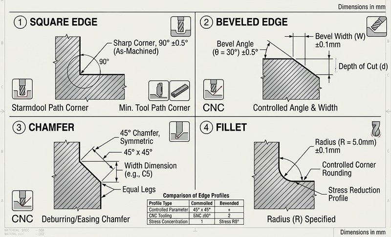
The visual test is whether the transition is straight or curved. A straight angled face reads as a bevel or a chamfer; a curved one is a fillet. Telling a bevel from a chamfer is not a visual question — that one is decided by the callout.
Ⅳ. Bevel vs. Chamfer: Are They the Same?
Not exactly, and the difference sits in usage rather than shape. Chamfer is the common drawing term for a small angled edge break, often 45° in common practice, and usually there to remove a sharp corner or lead in a fastener. Bevel is the broader term for an angled transition, and it often implies a larger face with a functional purpose: weld preparation, clearance, or a specified surface condition.
What governs the geometry is the callout, not the word. If the location, angle reference, size, and applicable tolerance are identical, the resulting geometry can be identical regardless of whether a drawing labels it a bevel or chamfer. Where the two words genuinely diverge is in expectation. A chamfer is often shown as a small angled edge break and may be 45° in common practice, but a drawing should not rely on that assumption when angle, size, fit, or inspection matters. A “bevel” with no angle is genuinely ambiguous and should not be left open.
For the radius-based alternative and the reasoning behind choosing between the two, see Keywin’s fillet vs. chamfer comparison.
Ⅴ. Why Are Bevels Used on Machined Parts?
- Edge break and handling safety — removing a sharp corner reduces cut risk during handling and assembly.
- Assembly lead-in — an angled face guides a pin, shaft, or bolt into a hole and reduces the chance of jamming or cross-threading.
- Edge damage protection — a sharp corner is the first feature to chip or deform in service; a beveled edge survives contact and handling better.
- Clearance for welding or a downstream process — weld groove preparation and some joining methods need angled faces with defined geometry.
- Appearance and defined edge quality — where an edge is visible or customer-facing, a consistent bevel is a specification rather than a finishing afterthought.
Not every bevel does all of these. A small edge break and a weld-preparation bevel are both bevels, and they are not interchangeable.
Ⅵ. How to Specify a Bevel on a Drawing
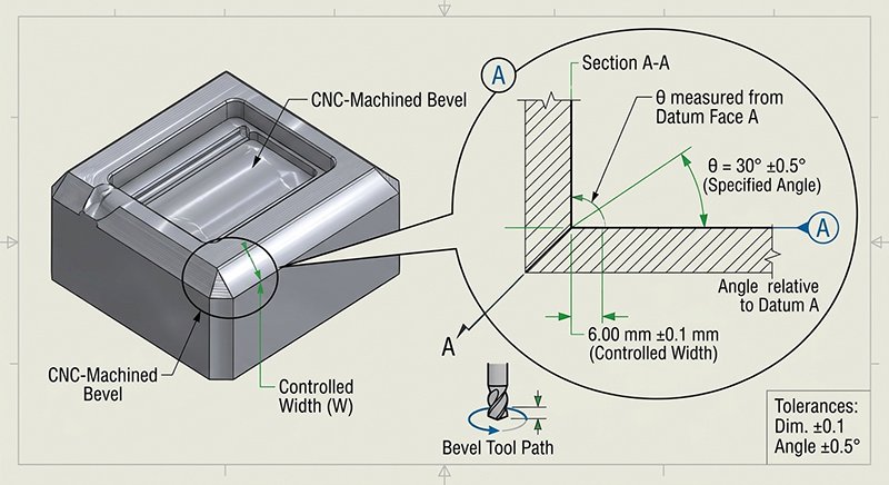
A quotable and inspectable callout includes:
- Location — which edges or features, and whether it applies to all edges or specific ones
- Bevel angle — the angle value, and the surface or plane it is measured from
- Width or length — the size of the angled face, which is what controls how much material is removed
- Adjacent reference — the datum or feature the angle is relative to
- Tolerance — on the angle and on the width, where either affects fit or function
- Deburring requirement — whether the edges created by the bevel must be deburred
- Post-finish condition — whether the callout applies before or after anodizing, plating, or coating
“Add bevel” fails every one of those. The supplier has to guess the angle, the size, and the location, and inspection has nothing to measure against.
Ⅶ. How Beveling Is Machined
Beveling follows part shape and tool access rather than one fixed method:
- Milling — a chamfer mill or an angled toolpath produces the bevel face; a standard end mill can also generate it with a tapered pass.
- Turning — on rotational parts, the angled face comes from the tool path on the lathe.
- Dedicated deburring and edge tools — for small, repetitive edge breaks where a machining pass is not economical.
- Multi-axis setups — when the bevel sits on a face that is not reachable from one fixed orientation, or when the feature follows a compound angle. The choice between indexed positioning and simultaneous cutting depends on the surrounding geometry, as explained in Keywin’s multi-axis machining guide.
The choice comes down to which tool can reach the edge at the required angle and what the surrounding geometry allows.
Where the bevel sits on a face that needs a second setup, most of the cost of the feature is the extra orientation rather than the bevel itself. Keywin’s CNC machining services cover how edge features are assessed on a real part.
Ⅷ. DFM Considerations for Bevel Edges
A simple, accessible bevel can add little machining time. Cost rises when the feature requires an additional setup, special tooling, difficult access, or tighter inspection:
- Tool access — a bevel on a face that needs an extra setup or a 5-axis orientation costs more in fixturing and cycle time than in cutting.
- Narrow or thin edges — a thin wall or a narrow land can deflect under the lateral load of the cut, and the required bevel width may exceed the material available.
- Internal corners — a rotating cutter leaves a radius. A bevel expected to meet a sharp internal corner will not; the corner carries the tool radius unless a relief or a secondary process is planned.
- Burrs on the new edges — beveling creates two new edges, and both can carry a burr. If deburring is required, state it on the drawing.
- Surface treatment interaction — coatings build thickness on edges, and a very small bevel can end up largely absorbed by a coating. Confirm whether the callout applies before or after finishing.
- Inspection method — small bevels are hard to measure consistently. Specifying how angle and width will be checked prevents a disagreement at receiving inspection.
Most of these are resolved by reviewing the bevel against the actual part geometry before quoting, which is cheaper than finding the problem during first-article inspection.
Ⅸ. Conclusion
A bevel is an angled face between two surfaces, defined by an angle and a size dimension — and in CNC machining the bevel meaning is whatever the drawing specifies, not a default 45°. Bevel vs. chamfer resolves through the callout: the word matters less than the angle, the width, and the function behind them. Where a bevel affects fit, welding, coating, or inspection, the geometry belongs in the drawing with a measurement reference, not in a note that says “add bevel.”
Upload your CAD model and drawing so Keywin’s engineering team can review bevel geometry, tool access, deburring needs, and inspection requirements.
Frequently Asked Questions
1. Is a bevel the same as a chamfer?
Not exactly. A chamfer is usually a small angled edge break and may be 45° in common practice. A bevel is the broader term for an angled face and often carries a functional purpose such as weld preparation or clearance. If location, angle reference, size, and tolerance match, the resulting geometry can be identical regardless of which word the drawing uses.
2. What is a bevel angle?
A bevel angle is measured from the reference surface identified on the drawing. The callout should also define the bevel’s size and location — see the drawing-specification section above.
3. How should a bevel be called out on a drawing?
State the location, the angle with its reference surface, the size of the angled face, and the tolerance that applies. The full list of what a quotable callout needs, including deburring and post-finish condition, is in the drawing-specification section above.
4. Can CNC machining produce custom bevel angles?
Many custom bevel angles can be CNC machined when tool access, surrounding geometry, workholding, material behavior, and inspection requirements allow. The supplier should review the drawing before confirming manufacturability.