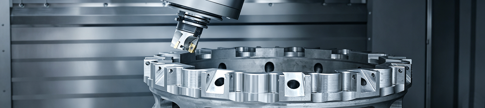
Multi-axis machining adds rotary motion to CNC milling so that the tool or workpiece can reorient during or between cuts, instead of moving only along X, Y, and Z. That orientation control is what makes features on multiple faces, angled holes, and deep cavities reachable without repeated fixturing. Not every complex part needs simultaneous 5-axis — indexed 3+2 or 4-axis machining often solves the same problem at lower cost. This guide explains how multi-axis CNC machining works and how to choose between the four common strategies.
Ⅰ. What Is Multi-Axis Machining?
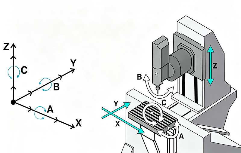
On a CNC mill, X, Y, and Z are linear axes: the tool or table travels in straight lines along them. A, B, and C are rotary axes that rotate around those linear axes — A pivots around X, B around Y, and C around Z. When a machine combines linear travel with at least one additional controlled rotary axis, the industry typically calls it multi-axis machining.
Multi-axis work splits into two motion families. In indexed machining, the rotary axes position the part or tool head and lock, and a conventional 3-axis toolpath then runs. In simultaneous machining, linear and rotary axes move together while material is being cut. Owning a 5-axis machine does not mean every job runs in continuous 5-axis motion — many parts made on 5-axis machines are actually cut in a series of 3+2 indexed positions.
Ⅱ. How Does Multi-Axis CNC Machining Work?
Linear and Rotary Axes
Rotary motion changes the angle between the tool and the workpiece. A fixed vertical spindle can only reach what is visible from straight above; adding rotation lets the tool approach a face from a different direction, or swings the workpiece so a new face points at the spindle.

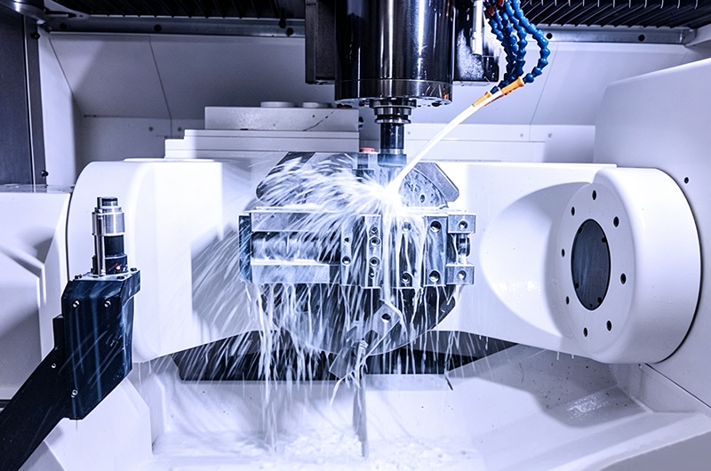
Not all machines achieve this the same way, so it pays not to assume a single architecture:
- Table-table machines carry both rotary axes in the table — the workpiece tilts and rotates while the spindle stays fixed.
- Head-head machines put both rotary axes in the spindle head — the tool pivots while the part stays still, which helps with heavy workpieces.
- Head-table machines split the rotation between the two, with one axis at the spindle and one at the table.
These configurations differ in maximum part weight, tool reach, and where collision risks concentrate, which is why two shops quoting the same “5-axis” part may propose different approaches.
Indexed Versus Simultaneous Motion
Indexed machining moves the rotary axes first, locks them, and then cuts. The cutting itself is 3-axis; the rotation only repositions the part between cuts. Setup counts drop because the machine repositions instead of an operator re-fixturing at the bench.
Simultaneous machining interpolates linear and rotary axes together during the cut, so the tool orientation changes continuously along the toolpath. This is what maintains a consistent tool angle across a curved surface or keeps a slim tool engaged in a deep, twisted channel.
Mastercam describes 3+2 machining the same way: the rotary axes position the part first, then a traditional 3-axis toolpath runs — which is distinct from true simultaneous multi-axis machining. Confusing the two is one of the most common specification errors on drawings and RFQs.
Ⅲ. 3-Axis vs. 4-Axis vs. 3+2 vs. 5-Axis Machining
| Method | Motion | Typical Parts | Main Advantage | Main Limitation |
|---|---|---|---|---|
| 3-axis | Cutting moves in X, Y, Z only | Plates, flat faces, standard pockets | Simple programming and fixturing | Multi-face features may need several setups |
| 4-axis | One rotary axis added (often A) | Circumferential holes, shafts, multi-side features | Rotates the part automatically | Limited capability for complex contours |
| 3+2 | Two rotary axes position, then lock | Angled holes, multi-face parts, inclined planes | Fewer setups, manageable programming | Not simultaneous 5-axis cutting |
| Simultaneous 5-axis | Linear and rotary axes interpolate together during cutting | Impellers, complex contours, deep cavities | Continuous tool-orientation control | Higher demands on programming, simulation, and collision avoidance |
More axes do not automatically equal a better machining strategy. Every step up the ladder raises machine-hour rates, programming effort, and simulation requirements. If a part can hold its tolerances across two 3-axis setups and those setups are cheap to repeat, that is the more economical route — the axis count is a means, not the goal.
Ⅳ. When Does a Part Need Multi-Axis Machining?
The deciding factor is part geometry, not the industry name on the project. These are the feature patterns that actually justify rotary motion.
Features on Multiple Faces
When pockets, holes, or machined faces wrap around several sides of a part, a 3-axis cell has to break the job into sequential setups. Each re-fixture adds handling time and introduces datum transfer between features cut in different setups. Multi-axis machining keeps those faces inside one setup by repositioning the part on the machine instead of at the bench.
Angled Holes and Inclined Surfaces
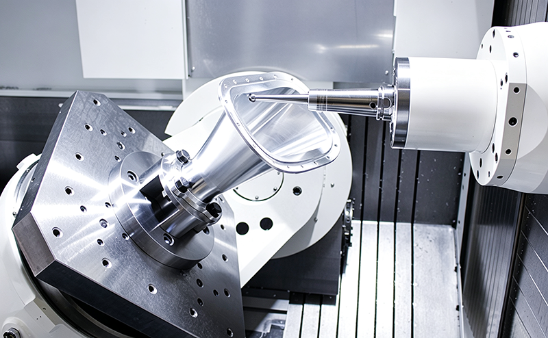
Holes at a fixed compound angle and planar faces tilted off the main datum planes are the classic case for indexed positioning. A 4-axis table handles features distributed around an axis; 3+2 handles holes and faces at arbitrary fixed angles. Simultaneous motion only becomes necessary when the required angle changes continuously along a path, not when it is simply “not parallel to Z.”
Deep Cavities and Tool-Access Problems
Deep pockets and tall walls force long tools with unfavorable length-to-diameter ratios, which invites chatter and deflection. Tilting the tool lets a shorter, stiffer cutter reach the same geometry at a better attack angle. Before assuming multi-axis is required, check the practical constraints: tool-holder clearance, fixture proximity, cutting-tool length, and the collision space around the part all still limit what is reachable, regardless of how many axes the machine has.
Continuous Curved Surfaces
Impellers, blisks (bladed disks), and free-form surfaces need the tool vector to follow the surface continuously — a fixed or indexed orientation cannot maintain a consistent contact angle across a compound curve. This is the domain of simultaneous 5-axis machining, where tool tilt is part of the toolpath itself rather than a setup decision.
Features With Tight Positional Relationships
When two critical features must hold a tight relationship to each other, cutting them in the same setup removes one source of variation — datum transfer between fixtures. Reducing re-fixturing can help control positional relationships this way. It does not guarantee a specific tolerance on its own; the achievable result still depends on the machine’s condition, calibration, and the cutting strategy, so treat multi-axis as one input to tolerance capability, not a promise.
Ⅴ. Benefits and Limitations of Multi-Axis Machining
| Where multi-axis helps | Where it costs or constrains |
|---|---|
| Fewer re-fixtures and less bench handling | Programming and post-processing are more complex |
| Less datum transfer between setups | Requires dependable machine simulation and collision checking |
| Better tool access to obstructed geometry | Fixturing and part placement still limit reach |
| Shorter, stiffer tools become usable in some cases | Machine-hour rates are usually higher |
| Better surface continuity on compound curves | Simple parts are not automatically cheaper |
| Opportunity to shorten total lead time | A second setup or secondary operation may still be needed |
These benefits are conditional, and the conditions are the useful part. Fewer setups only pays off when the features actually share a setup — a part with one multi-face feature and everything else flat may still be cheapest in two simple operations. Shorter tools only help when tilting genuinely replaces reach. Surface-continuity gains matter on compound curves, and nowhere else.
That framing goes further than the standard benefit list. Mastercam’s overview covers the familiar advantages — fewer setups, shorter tools, surface finish, complex-part capability — but whether each one materializes depends on the part in front of you. Treat the left column above as “check if the condition applies,” not as a default outcome.
Ⅵ. How to Choose the Right Machining Strategy
Start from the part, then match the strategy:
| Part Situation | Consider First | Why |
|---|---|---|
| Mostly flat faces, holes, and standard pockets | 3-axis | Avoids unnecessary equipment cost |
| Features distributed around an axis | 4-axis | The machine rotates the part automatically |
| Multi-face features and holes at fixed angles | 3+2 | Fewer setups without continuous rotation |
| Continuous free-form surfaces | Simultaneous 5-axis | Tool direction must change continuously |
| Several critical features on one datum scheme | 3+2 or 5-axis | Reduces datum transfer |
| Simple geometry but higher volumes | Compare full process costs | Multi-axis is not automatically the cheapest route |
Before committing, put these six questions to the part:
- Can the tool reach every critical surface from a fixed orientation?
- How many faces of the part actually need machining?
- Which features must stay inside one datum scheme?
- Will the tool, holder, or spindle interfere with the fixture or the workpiece?
- Is 3+2 already sufficient for the angles involved?
- Do the setup reductions offset the higher programming and machine-hour cost?
If the answers do not point clearly at one strategy, a manufacturability review on the actual CAD model usually settles it faster than reasoning from a spec sheet — see Get a Multi-Axis Machining Quote below.
Ⅶ. Typical Multi-Axis Machining Applications
- Aerospace brackets and structural parts — multi-face pockets, thin walls, and features that must share a datum scheme across sides.
- Impellers and bladed components — continuous curved surfaces that require simultaneous tool-orientation control.
- Medical and surgical components — small, complex geometries with angled features and tight finish requirements.
- Robotics housings — enclosures with ports, bosses, and mounting faces on several sides.
- Automotive prototypes — one-off and low-volume parts where consolidating setups shortens iteration loops.
- Molds and complex inserts — deep cavities and steep walls that demand tilted tool approaches.
- Precision parts with angled or multi-face features — the broad category where indexed 3+2 does most of the work.
These are applications where the geometry justifies the strategy — the same industries also produce thousands of parts that are better suited to plain 3-axis work.
Ⅷ. Design and Quotation Checklist
To get a usable multi-axis machining quote, prepare:
- 3D CAD model — the primary input for tool-access and strategy evaluation.
- 2D drawing — captures requirements the model does not carry.
- Material and temper — affects cutting parameters, tooling, and cost.
- Tolerances and datum scheme — shows which features must share a setup.
- Surface-finish requirements — drives strategy and tool selection on curved faces.
- Critical features list — tells the engineer what to protect when planning setups.
- Required quantity — changes the economics between strategies.
- Inspection requirements — indicates how setup decisions will be verified.
- Areas that cannot contain tool marks — clamp and fixture placement depends on these zones.
- Permitted manufacturing changes — small geometry concessions sometimes remove the need for an extra axis entirely.
Ⅸ. Get a Multi-Axis Machining Quote
Upload your CAD model and technical drawing for a manufacturability review. Keywin can evaluate whether 3-axis, indexed multi-axis, or five-axis machining is the more practical route for your part geometry, tolerances, quantity, and cost target
FAQs
1. Is multi-axis machining the same as 5-axis machining?
No. Multi-axis machining is the umbrella term for any machining that adds rotary motion to linear X/Y/Z movement, which includes 4-axis and indexed 3+2 work. Simultaneous 5-axis machining is one specific member of that family, where all five axes interpolate together during the cut. Many parts described as “5-axis parts” are in practice produced using indexed 5-axis machining, so the two terms should not be used interchangeably.
2.What is the difference between 3+2 and simultaneous 5-axis machining?
In 3+2 machining, the two rotary axes position the part at a fixed angle and lock before cutting; the cut itself runs as a standard 3-axis toolpath. In simultaneous 5-axis machining, rotary and linear axes move together while cutting, so tool orientation changes continuously along the path. 3+2 suits holes and faces at fixed angles; simultaneous motion suits impellers, blades, and other continuous compound curves.
3. Is multi-axis machining always more accurate?
No. Machining in one setup removes datum-transfer error between fixtures, which can improve consistency between features. Final accuracy still depends on machine condition and calibration, thermal behavior, tooling, workholding, and the cutting strategy. An unstable or poorly simulated multi-axis program can produce worse results than a well-executed two-setup 3-axis process, so accuracy is a process outcome rather than an axis-count property.
4. Can multi-axis machining reduce part cost?
Sometimes. The savings come from consolidated setups, less fixturing, shorter cycle times, and reduced handling. Against that, multi-axis machines usually carry higher hourly rates, and programming plus simulation effort is greater. For parts where one indexed setup replaces three bench re-fixtures, cost often drops. For simple parts or very small quantities, the higher rate and programming overhead can make multi-axis the more expensive option.
5.When is 3-axis machining sufficient?
When every critical surface is reachable from one fixed tool direction, the part needs no continuous tool-orientation control, and tolerances do not require all features to share one setup. Flat plates, housings with accessible features, and parts whose secondary faces can be machined cheaply in a second simple setup are all candidates. Adding axes to such parts raises cost without changing the result.